P-164000341 8-10 kVA, 50/60 Hz (1-phase input) &
8-15 kVA, 50/60 Hz (3-phase input)
59
Revision 1 User's Guide
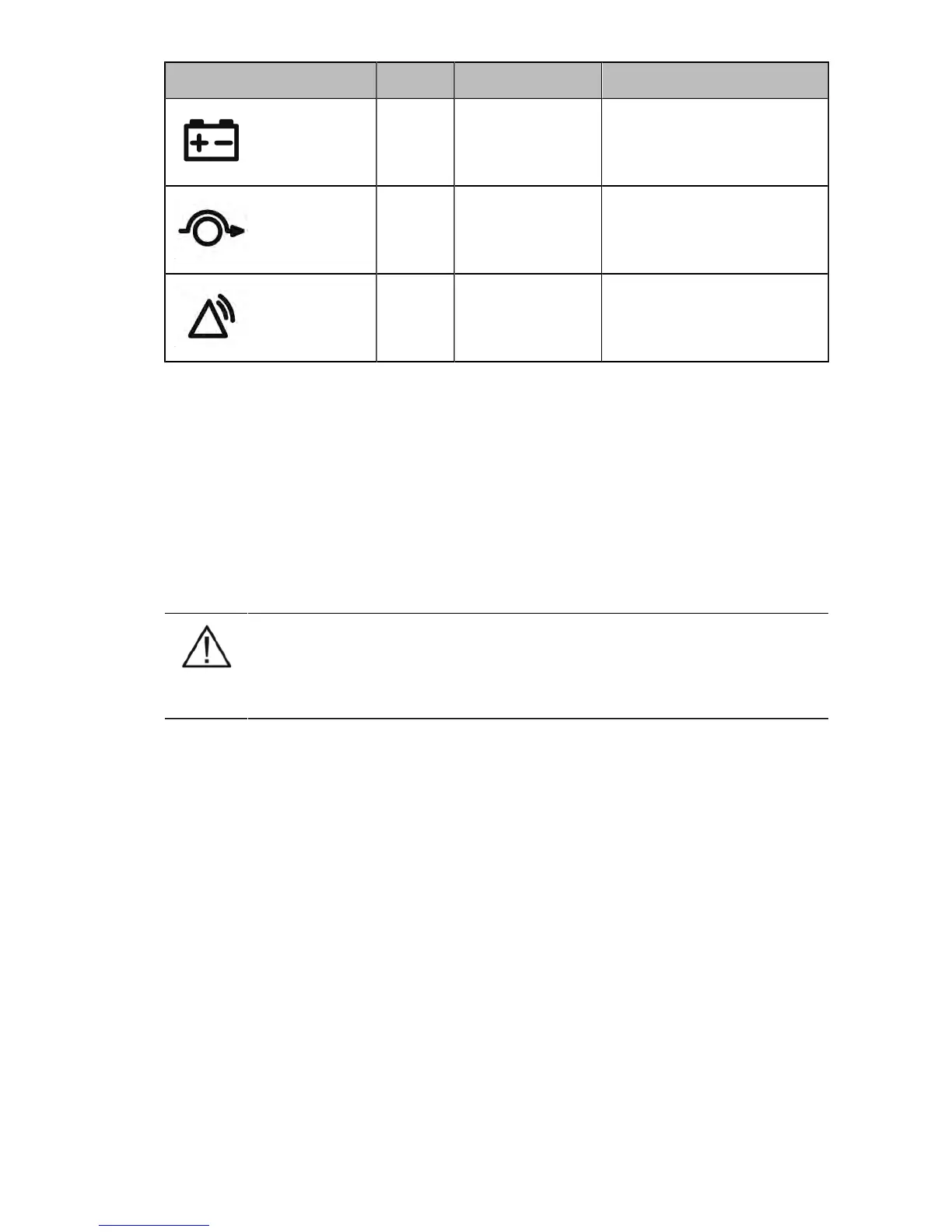
Graphical sign LED Description Note
Yellow 1 UPS is in battery
mode.
Yellow 2 UPS is in bypass
mode.
Red UPS has an active
alarm.
Blinking when new alarm is not
reset and still active.
Table 9-3: Description of the LED indicators
9.3 Maintenance bypass switch (MBS) operation
The UPS unit comes with a maintenance bypass switch as a standard or optional feature, depending
on the ordered configuration. The operation of the MBS is allowed for a trained person only who
is familiar with the UPS behavior and functions. The full UPS wiring diagram with a MBS switch is
presented in the installation part of the manual.
9.3.1 Internal maintenance bypass switch operation
NOTE
The internal MBS consists of two switches and failure to understand the correct sequence may
drop the critical load.