38 8-10 kVA, 50/60 Hz (1-phase input) &
8-15 kVA, 50/60 Hz (3-phase input)
P-164000341
User's Guide Revision 1
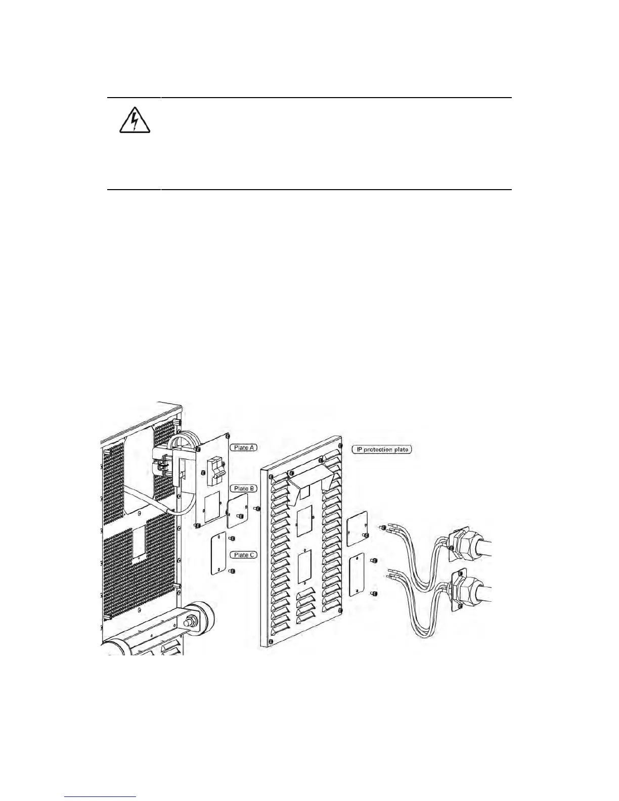
the whole system is ready. Remove the IP protection plate first and remove the plate A on the
rear side of the EBC to connect cables to EBC’s terminal block X6. Bring cables outside from
the EBC by removing the cover plate B. Place the plate A back to the original position and use
the cover plate B as a cable clamp.
WARNING
If an internal battery string is installed and already connected to the terminal block
there is a danger of a lethal electric shock. Turn F1 battery breaker from the UPS unit
to OFF position and measure the voltage across the terminals to be 0 (zero) before any
operations with terminal X3.
5. If the system consists two or more EBC connect first the EBCs parallel as follows:
a) Connect the cables to second EBC in the same way as guided in point four (4) of this
installation procedure.
b) Remove the cover plate C of the first EBC and connect cables to terminal block X6. Use the
cover plate C as a cable clamp.
6. When all the EBCs are connected parallel, make sure that F1 battery breaker is in OFF position
before connecting cables to terminal block X3 of the UPS unit. Otherwise the terminal block X3
is live. To be on the safe side, measure the voltage across the terminals to be 0 (zero).
7. After installation connect disconnected battery cables to strings, check that the removed plates
on right positions, remove safety wires from circuit breakers and turn breakers of EBCs and the
UPS to ON position.
8. Finally change the Number of 32 pcs. battery strings from User Settings. SETTINGS -> USER
SETTINGS -> NUMBER OF BATTERY STRINGS.
Figure 6-18: Cable connections of the External Battery Cabinet