3
Instruction Leaflet IL 29C101H
Effective January 2011
Installation Instructions for EHD, EDB, EDS, ED, EDH, EDC, FDB, FD,
HFD, FDC, HFDDC Circuit Breakers and Molded Case Switches
EATON CORPORATION www.eaton.com
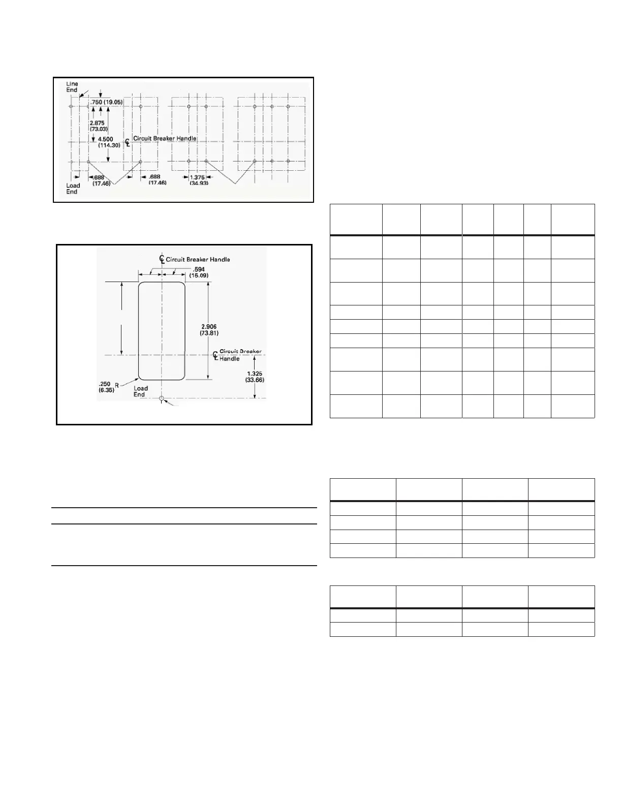
Figure 2. Circuit Breaker Mounting Bolt Drilling Plans
Figure 3. Circuit Breaker Esutcheon Dimensions
2-4. If an optional terminal end cover is to be installed with the
circuit breaker (usually line end only), it must be positioned before
cable is connected to terminals.
DCAUTION
WHEN ALUMINUM CONDUCTORS ARE USED, THE APPLICATION OF
A SUITABLE JOINT COMPOUND IS RECOMMENDED TO REDUCE THE
POSSIBILITY OF TERMINAL OVERHEATING. TERMINAL OVERHEATING CAN
CAUSE NUISANCE TRIPPING AND DAMAGE TO THE CIRCUIT BREAKER.
2-5. After mounting the circuit breaker, line and load terminals and
accessory leads should be connected. (See accessory schematic
diagram on side of circuit breaker.)
ote:N If terminal shield or interphase barriers are to be installed on the circuit
breaker, install them after the terminals are connected.
3
Poles
(M4
x
.07)
Poles
3
Poles
2
Poles
1
Pole
.164-32 Tap Holes
(M4 x .07)
.164-32 Tap Holes
(M4 x .07)
4
2913
I
.188 (4.78 mm) Dia. Hole for
Access to Push-to-Trip
Line
End
2.313
(58.75)
2-6. If required, install terminal shield on circuit breaker cover with
mounting screws provided.
2-7. If required, install an interphase barrier by sliding barrier into
dovetail grooves between terminals.
2-8. After the circuit breaker is installed, check all mounting hard-
ware and terminal connecting hardware for correct torque loading.
Torque values for line/load terminals are given in Tables 1, 2, and 3
and on the circuit breaker nameplate.
ote:N See Section 5 for additional details for HFDDC.
Table 1. Terminal Types
Terminal
Catalog
Number
Terminal
Body
Material
Screw
Head Type
AWG
Wire
Range
Metric
Wire
Range
Wire
Type
Torque
Value, Lb.
in.(N.m)
3TA225FD
Aluminum 3/16 Socket
Hex
#4-4/0 25-95 Cu/Al 120 (13.6)
3TA225FDM
Aluminum 5mm Socket
Hex
#4-4/0 25-95 Cu/Al 120 (13.6)
3TA225FDK
b
Aluminum 5/16 Socket
Hex
#6-300 16-150 Cu/Al 275 (31)
3TA100FD
Aluminum Slotted #14-1/0 2.5-5.0 Cu/Al See Table 2
3TA50FB
Aluminum Slotted #14-#4 2.5-16 Cu/Al See Table 2
3T100FB
Steel Slotted #14-1/0 2.5-50 Cu/Al See Table 2
3T150FB
Stainless
Steel
Slotted #4-4/0 25-95 Cu
Only
See Table 2
3TA150F3K Aluminum 5/32 Socket
Hex
#14-2 2.5-25 Cu/Al 70 (7.9)
3TA150F6K Aluminum 3/32 Socket
Hex
#14-6 2.5-10 Cu/Al 25 (2.8)
Note: Terminal wire connectors are UL listed for standard wire sizes as defined in UL 486A
and UL486B.
Package of Three
b
Individual terminal identified as TA225FD1
Table 2. Terminal Torque Values for Slotted Head
Metric Wire
Range
Torque Value N.m AWG Wire Range Torque Value,
Lb.-In.
2.5-6 3.96 #14-#10 35
10 4.52 #8 40
16-25 5.09 #6-#4 45
35-95 5.65 #3-4/0 50
Table 3. Bolted Connections (Keeper Nut or End Cap)
Termination
Catalog Number
Screw Head Type Nut Thread Size Torque Value Lb.
In. (N.m)
KPR1A/KPR1AM Upper Supplied 10-32/M5 35 (4.0)
KPEKxxx Slotted 10-32/M5 35 (4.0)
 Loading...


