29
© 2017 Eaton. All rights reserved
2018.12.12
LAS/VAS Auxiliary Section Assembly and Installation | Service Procedures TRSM0940
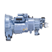
3. Place the Auxiliary Main Shaft positioning cone around
the splines of the shaft, set the Main Shaft upright with
the Synchronizer facing down.
Note: Con
e size must be 4-3/8" tall with a 4" inner
diameter. PVC pipe is recommended.
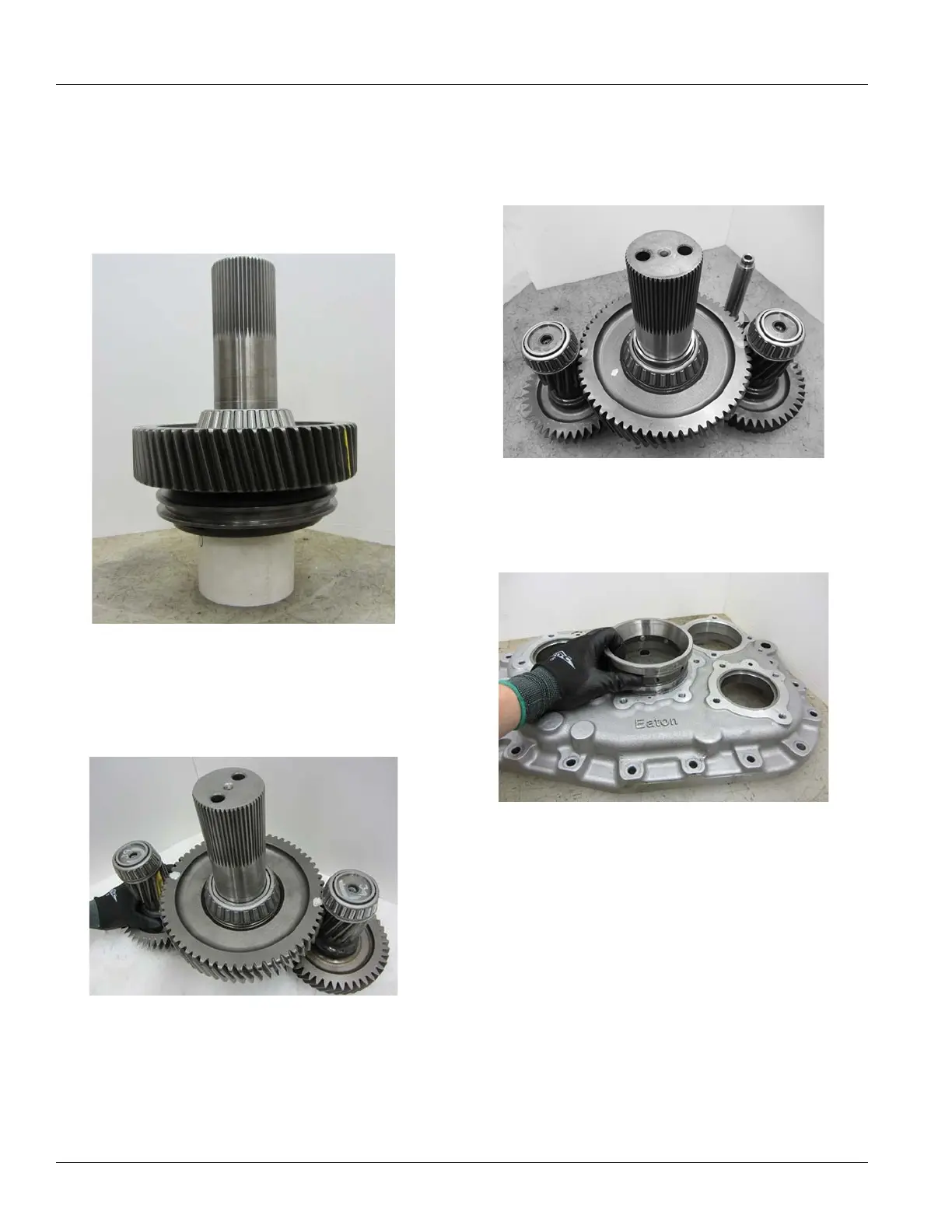
4. Mo
ve the upper and lower Counter Shafts into place on
the Range Reduction Gear lining up the timing marks
previously made.
5. Position
the Range Shift Yoke on the Range Synchro-
nizer Sliding Clutch with the shaft aligned above the
lower Count
er Shaft.
6. In
stall the double bearing race into the Auxiliary Case
with the race flange out.
7. Before
installing the Main Case, remove excess RTV
sealant from the mating surfaces of the Auxiliary Case
and Main Case.
 Loading...