2018.12.12
© 2017 Eaton. All rights reserved
186
TRSM0940 Service Procedures | Reverse Switch Testing, Removal and Installation
Reverse Switch Testing, Removal and Installation
Special Instructions
The Reverse Switch is a normally open ball switch. When
the transmission is shifted into Reverse, a ramp on the
Reverse Shift Yoke contacts and raises a pin. The pin
depresses the ball on the switch, which closes the switch
contact, allowing current to flow through the switch and
light up the vehicle backup lights.
Special Tools
None
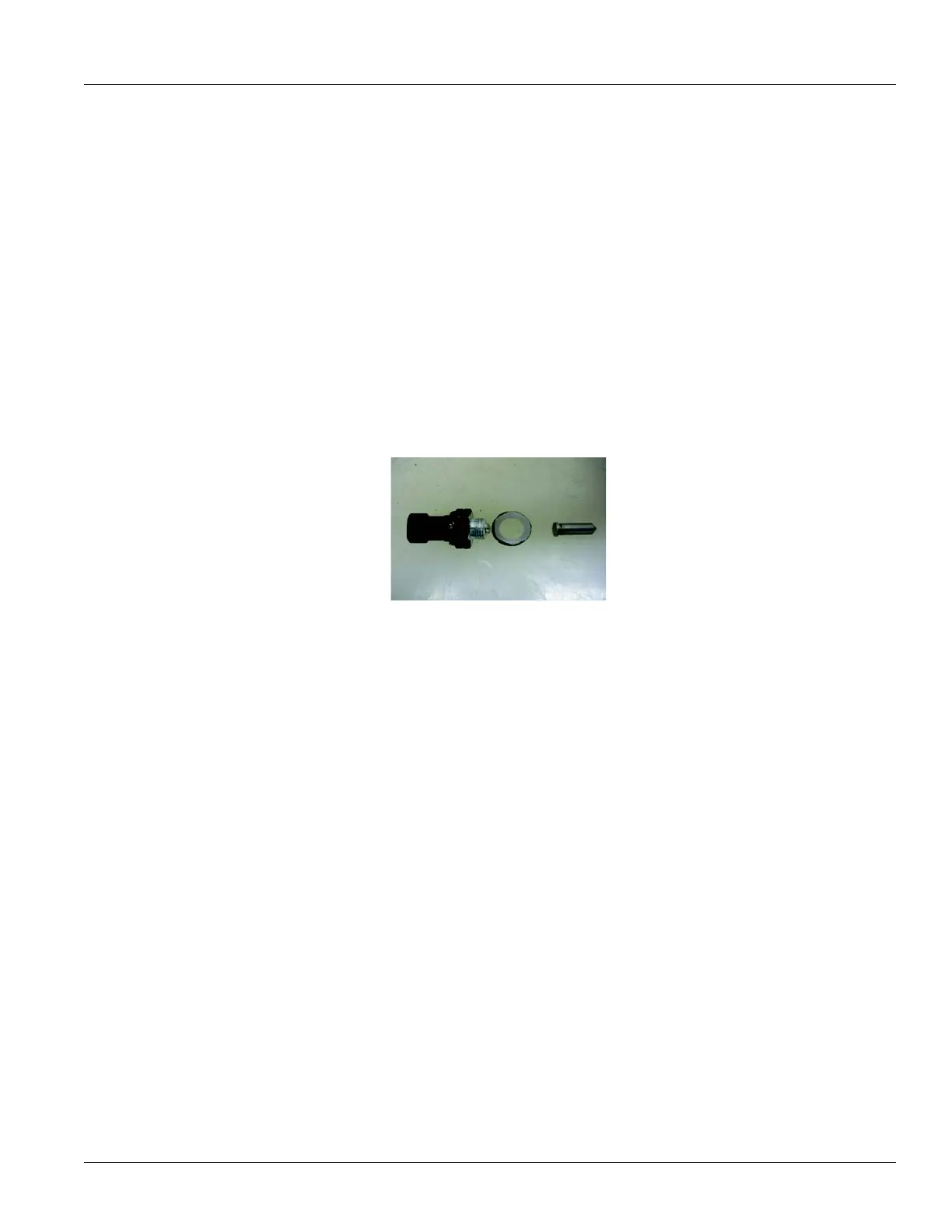
Component Identification
Reverse Switch Testing
1. Disconnect the wiring from the switch by lifting the
connector locking tab and pulling the connector out of
the switch.
2. Connect
an ohm meter to test for continuity.
3. Place the
Transmission Shift Lever in any position
except Reverse. If the switch is working properly, the
ohm meter should read open or infinity. If it is not,
remove the switch and recheck it for continuity.
Replace as necessary.
4. Place the Transmission
Shift Lever in the Reverse posi-
tion. If the switch is working
properly, the ohm meter
should register continuity or a small reading. If it does
not, remove the switch and recheck it for continuity.
Replace as necessary. Also, check for the presence of
the Reverse Pin.
Reverse Switch Removal
1. Disconnect the OEM wiring. Remove the Reverse
Switch using a 22 mm or 7/8” deep well socket or box
end wrench.
2. Check for the presence
of the Reverse Pin in the bore
under the switch.
3. While watching
the Reverse Pin, move the Transmis-
sion Shifter between the Reverse position and any
gear. Th
e pin should raise when the Transmission is
shifted to Reverse and lower when the Transmission is
in Neutral. If the pin does not raise and lower, inspect it
to see if something is causing it to stick, and inspect it
for wear. Also, remove the Shift Tower and check for
wear on the Reverse Yoke Ramp. This ramp can be
seen through the shifter opening.
1. Reverse Switch
2. Gasket
3. Actuating Pin
 Loading...