Board. And check procedures are as follows.
1. Communication cable connection check.
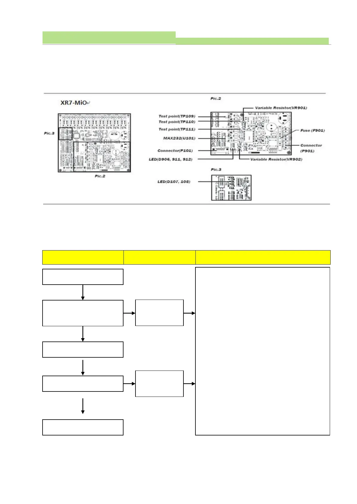
2. LED (D107, 108) light check. Normal: D107 flickering
when parameters are being set (green light)
Abnormal: D108 light ON (Red color)
3. LED (D906, 911, 912) check. Normal: D906 light on
before Power On .D911, 912 light ON after Power ON.
Abnormal: No LED light ON after Power ON.
4. Connector (P901) checks and measures the voltage.
(Normal: 230VAC)
5. Check the Fuse (F901)
6. Check voltage between Test point (TP109) and Test
point (TP110) (Normal: 7.5VDC ± 0.1V)
7. If the voltage (TP110) is not correct, adjust VR901 to
fix it at 7.5VDC.
8. Check voltage between Test point (TP109) and Test
point (TP111) (Normal: 15VDC ± 0.1V)
9. In case the voltage from TP111 is wrong, adjust
VR902 to fix it at 15VDC.
10. Check RX signal between MAX232 (U101) pin 13 and
Test point (TP109). Normal: see the next page
(Oscilloscope waveform)
11. Check TX signal between MAX232 (U101) pin 14 and
Test point (TP109). Normal: see the next page
(Oscilloscope waveform)