STP-iXR1606 Turbomolecular Pump
MT-79E-001-D
Page 44
INSTALLATION
3
3.5.1 Vacuum piping method
1. Attach the inlet port to the high vacuum side.
(Refer to Section 2.1, "STP pump specification" for maximum working pressure).
2. Attach the outlet port to the inlet port flange of the backing-pump (primary side pump).
(Refer to Section 2.1, "STP pump specification" for allowable backing pressure).
Note: Maximum flow for water cooled is applicable under the condition listed in Section 2.3, "Water
cooling use condition".
3.6 Introducing N
2
gas (for the STP pump equipped with purge port)
When pumping reactive or corrosive gas, gas including hydrogen, introduce a dry N
2
gas or other gas
into the STP pump in order to protect the inside of the STP pump. To isolate (Lockout/Tagout) the
purge gas N
2
, introduce a dry N
2
gas through the electromagnetic vent. valve, needle valve or similar
valve (must be prepared by the customer) from the purge port.
When exhausting a gas which has low heat conductivity such as Ar gas, the temperature of rotor
blade will increase. Introduce a dry N
2
gas into the STP pump through the purge port in order to
decrease the temperature of rotor blade and exhaust the large amount of Ar gas.
For instructions on how to introduce the purge gas, see Section 4.1.2.
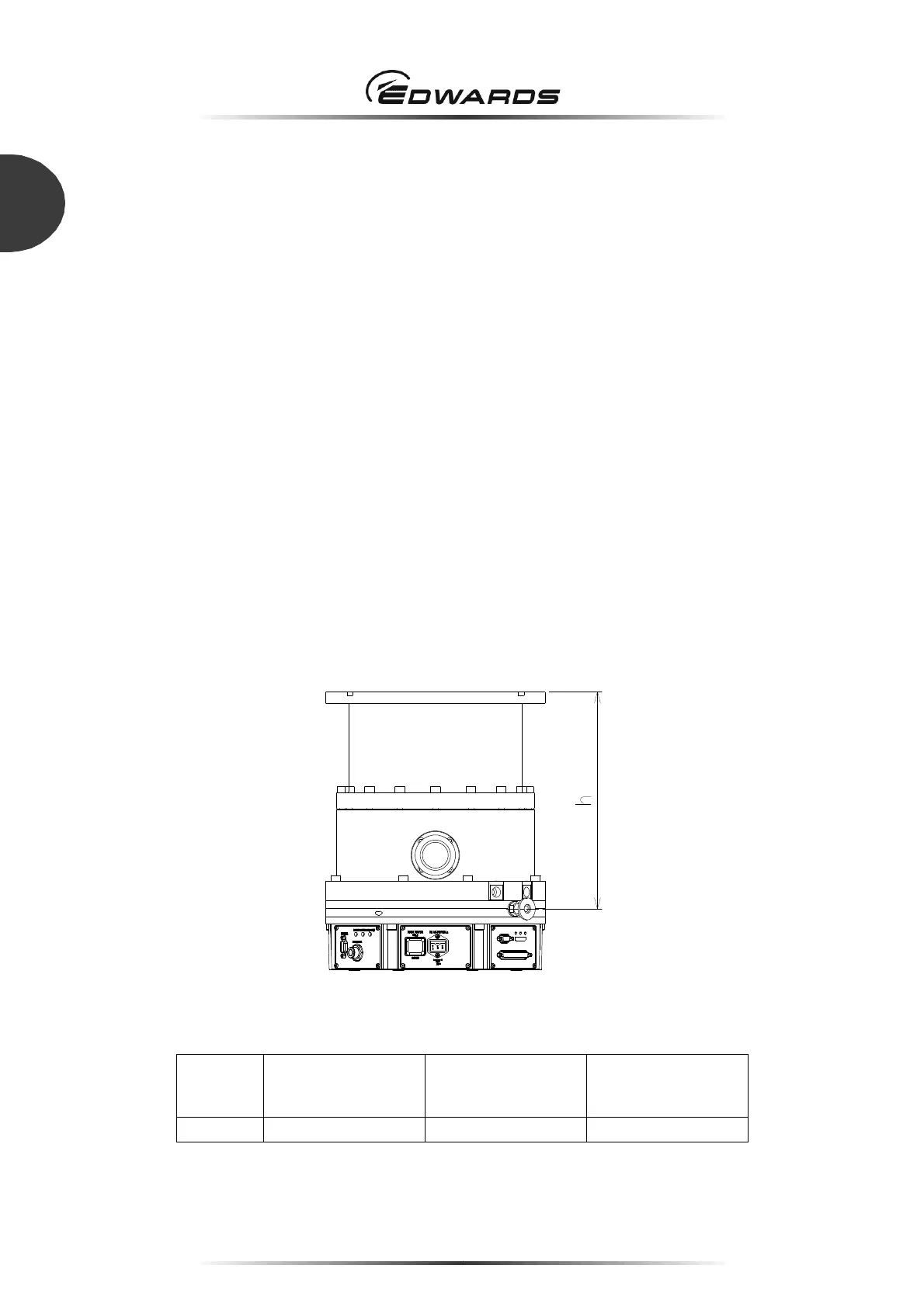
h Height of purge port
Inlet port
flange
VG200 / VG250
ISO200F / ISO250F
ICF305
VG150 / ISO160F
ICF203
ICF253
h 296 336 334
Figure 25 - Height of purge port

 Loading...