8
BASIC
OPERATIONS
④ Connecting to a device with an analog RGB input port
Connect a commercially available RGB cable to the [ ] port on the rear
panel.
⑤ Connecting to a device with an analog RGB output port
Connect a commercially available RGB cable to the [ ] port on the rear
panel.
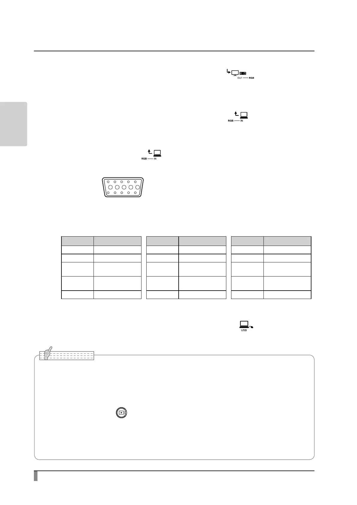
■ Specications of the [ ] port
Signal allocation
10
9 876
15 14 13
minal (Female)
12 11
Video signal
Horizontal synchronized signal
Vertical synchronized signal
Analog 0.7V (p-p) 75Ω terminated
TTL level
(Positive/negative polarity)
TTL level
(Positive/negative polarity)
Pin assignment
Pin No. Name Pin No. Name Pin No. Name
1 Video signal (Red) 6 Video signal (Red) 11 GND
2 Video signal (Green) 7 Video signal (Green) 12 N.C
3 Video signal (Blue) 8 Video signal (Blue) 13
Horizontal
synchronizing signal
4 N.C 9 N.C 14
Vertical
synchronizing signal
5 GND 10 GND 15 N.C
⑥ Connecting to a computer with a USB cable
Connect a commercially available USB cable to the [ ] port on the rear
panel.
• If the displayed image is o-center, adjustment of the horizontal and vertical position should be
made from the connected device.
• In some cases, vertical stripes may appear on the display device such as a projector and a monitor.
This can be reduced by adjusting the “clock phase” function of the connected device.
• When using a computer with an external output mode, set the computer to the external output
mode after pressing the [ ] button on the operating panel.
• We recommend using a compliant USB cable.
• If you plug into a USB cable with the power on, the computer may not recognize the product.
• Depending on the computer's USB environment or the peripheral equipment, image transfer may
be disrupted.
Note
 Loading...