Step 4: Private LAN cables
121
Connect Cables for a Direct-connected VG8
EMC CONFIDENTIAL
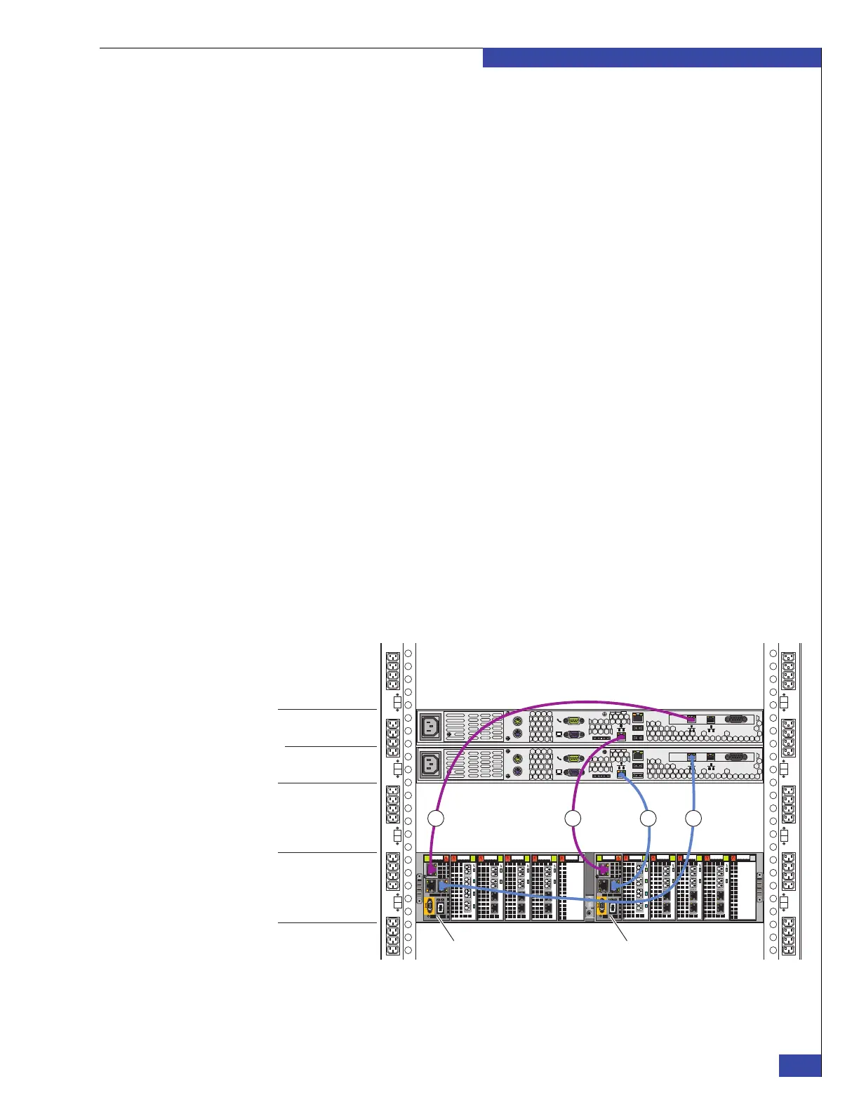
4. If required, verify that an RJ-45 Ethernet cable connects from port 2 on
management module B in blade enclosure 0 (blades 2 and 3) to the port labeled B
on CS 1. This is cable #4 in Figure 85 on page 121.
5. Verify that an RJ-45 Ethernet cable connects from port 0 on management
module B in blade enclosure 0 (blades 2 and 3) to port 1 on management
module B in blade enclosure 1 (blades 4 and 5). This is cable #5 in Figure 86 on
page 122.
6. Verify that an RJ-45 Ethernet cable connects from port 0 on management
module A in blade enclosure 0 (blades 2 and 3) to port 1 on management
module A in blade enclosure 1 (blades 4 and 5). This is cable #6 in Figure 86 on
page 122.
7. If required, verify that an RJ-45 Ethernet cable connects from port 0 on
management module B in blade enclosure 1 (blades 4 and 5) to port 1 on
management module B in blade enclosure 2 (blades 6 and 7). This is cable #7 in
Figure 86 on page 122.
8. If required, verify that an RJ-45 Ethernet cable connects from port 0 on
management module A in blade enclosure 1 (blades 4 and 5) to port 1 on
management module A in blade enclosure 2 (blades 6 and 7). This is cable #8 in
Figure 86 on page 122.
9. If required, verify that an RJ-45 Ethernet cable connects from port 0 on
management module B in blade enclosure 2 (blades 6 and 7) to port 1 on
management module B in blade enclosure 3 (blades 8 and 9). This is cable #9 in
Figure 86 on page 122.
10. If required, verify that an RJ-45 Ethernet cable connects from port 0 on
management module A in blade enclosure 2 (blades 6 and 7) to port 1 on
management module A in blade enclosure 3 (blades 8 and 9). This is cable #10 in
Figure 86 on page 122.
Figure 85 Private LAN cables to CS 0 and CS 1
AB
Serial
console
MGMT
CS
B
MODEM plug
VGA socket
A
0
123
0
123
0
12 3
0
1
23
0
12 3
0
12 3
0
12 3
0
1
23
0
12 3
0
12 3
Serial
console
MGMT
CS
B
MODEM plug
VGA socket
A
CNS-001691
Management
module B
Blade enclosure 0
Control Station 0
Control Station 1
2134
Management
module A
 Loading...