Safety
information
Product
information
Mechanical
installation
Electrical
installation
Getting
started
User Menu A Commissioning
Advanced
Parameters
Diagnostics Optimization CT MODBUS RTU Technical Data
E300 Design Guide 423
Issue Number: 1
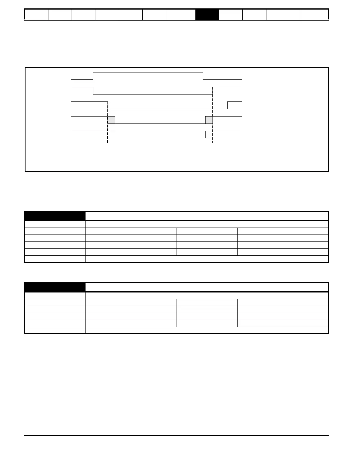
To ensure that the soft-start is in the correct state to protect the drive and to ensure that the under-voltage condition is detected correctly the following
additional restrictions are applied:
1. The soft-start cannot change from the active state (i.e. internal soft-start contactor closed) unless the d.c. link voltage is above the upper under-
voltage threshold or Under Voltage System Contactor Closed (O16) = 1.
2. The Under Voltage Contactor Close Output (O15) parameter is set to 1 if the d.c. link voltage is above the upper under-voltage threshold or the
Final drive enable = 1. The Under Voltage Contactor Close Output (O15) is only set to 0 if the soft-start is fully active.
The following diagram shows how these restrictions apply to the system timing when Lower Threshold ≤ D.c. Bus Voltage (J65)
Backup Supply Mode for frame size 07 drives and larger: (LV Supply Mode Enable (O12) = 1)
Backup supply mode is intended to provide a smooth transition, without disabling the drive, from a high voltage a.c. supply to a low voltage d.c.
backup supply and vice versa. The following diagram is a simple representation of the power circuit required. This does not include the necessary
circuit protection components or possible battery charger, etc.
See Standard Under Voltage Threshold (O11). Also see User Supply Select (O10) for details of when and how drive parameters can be saved, and
when a PSU 24 V trip can occur.
See Standard Under Voltage Threshold (O11). Also see User Supply Select (O10) for details of when and how drive parameters can be saved, and
when a PSU 24 V trip can occur.
O12 LV Supply Mode Enable
Mode Open-Loop, RFC-A, RFC-S
Minimum 0 Maximum
1
Default 0 Units
Type 1 Bit User Save Update Rate Background read
Display Format Standard Decimal Places 0
Coding RW
O13 Low Under Voltage Threshold Select
Mode Open-Loop, RFC-A, RFC-S
Minimum 0 Maximum
1
Default 0 Units
Type 1 Bit User Save Update Rate Background read
Display Format Standard Decimal Places 0
Coding RW
-voltage
Active (L19)
Under-voltage timing with Back-
(O12) = 1
(Frame sizes 07 and smaller and d .c. link voltage between the upper and lower under -voltage threshold )
Final drive enable
-voltage
System Contactor
Close (O15)
-voltage
System Contactor
Closed (O16)
Soft-start cannot change to inactive state
until Under-voltage System Contactor
Closed (O16) = 0
-voltage System Contactor Close
(O15) is not set to one until the soft-start
is fully active

 Loading...
