Safety
information
Product
information
Mechanical
installation
Electrical
installation
Getting
started
User Menu A Commissioning
Advanced
Parameters
Diagnostics Optimization CT MODBUS RTU Technical Data
424 E300 Design Guide
Issue Number: 1
See Standard Under Voltage Threshold (O11).
See Standard Under Voltage Threshold (O11).
See Standard Under Voltage Threshold (O11).
For frame size 07 drives and larger, which use a d.c. link charge system based on a half controlled thyristor input bridge, the rate at which the d.c. bus
is charged can be reduced by setting Slow Rectifier Charge Rate Enable (O17) to one. This will reduce the charging current which may be required if
significant additional capacitance is added to the d.c. link to prevent rupturing of input fuses.
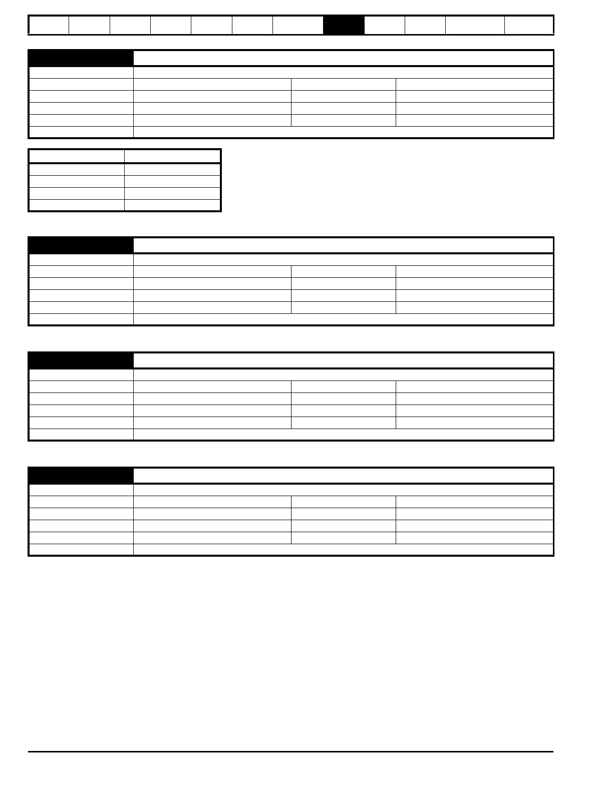
O14 Low Under Voltage Threshold
Mode Open-Loop, RFC-A, RFC-S
Minimum -VM_LOW_UNDER_VOLTS Maximum VM_LOW_UNDER_VOLTS
Default See exceptions below Units V
Type 16 Bit User Save Update Rate Background read
Display Format Standard Decimal Places 0
Coding RW, VM, RA
Voltage Default Value
200V 175
400V 330
575V 435
690V 435
O15 Under Voltage Contactor Close Output
Mode Open-Loop, RFC-A, RFC-S
Minimum 0 Maximum
1
Default Units
Type 1 Bit Volatile Update Rate 4 ms write
Display Format Standard Decimal Places 0
Coding RO, ND, NC, PT
O16 Under Voltage System Contactor Closed
Mode Open-Loop, RFC-A, RFC-S
Minimum 0 Maximum
1
Default 0 Units
Type 1 Bit Volatile Update Rate 4 ms read
Display Format Standard Decimal Places 0
Coding RW
O17 Slow Rectifier Charge Rate Enable
Mode Open-Loop, RFC-A, RFC-S
Minimum 0 Maximum
1
Default 0 Units
Type 1 Bit User Save Update Rate Background read
Display Format Standard Decimal Places 0
Coding RW

 Loading...
