Safety
information
Product
information
Mechanical
installation
Electrical
installation
Getting
started
User Menu A Commissioning
Advanced
Parameters
Diagnostics Optimization CT MODBUS RTU Technical Data
E300 Design Guide 99
Issue Number: 1
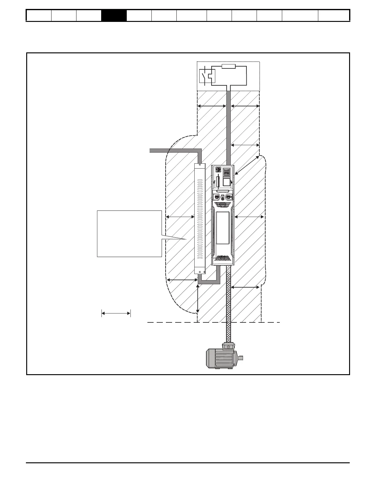
4.17.1 Cable layout
Figure 4-31 shows the clearances which should be observed around the drive and related ‘noisy’ power cables by all sensitive control signals / equip-
ment.
Figure 4-31 Drive cable clearances
Optional braking resistor and overload
Do not place sensitive
(unscreened) signal circuits
in a zone extending
300 mm (12”) all around the
Drive, motor cable, input
cable from EMC filter and
unshielded braking resistor
cable (if used)
300mm
(12in)

 Loading...
