13
Reference Manual
00809-0100-4840, Rev CB
Section 3: Installation
February 2015
Installation
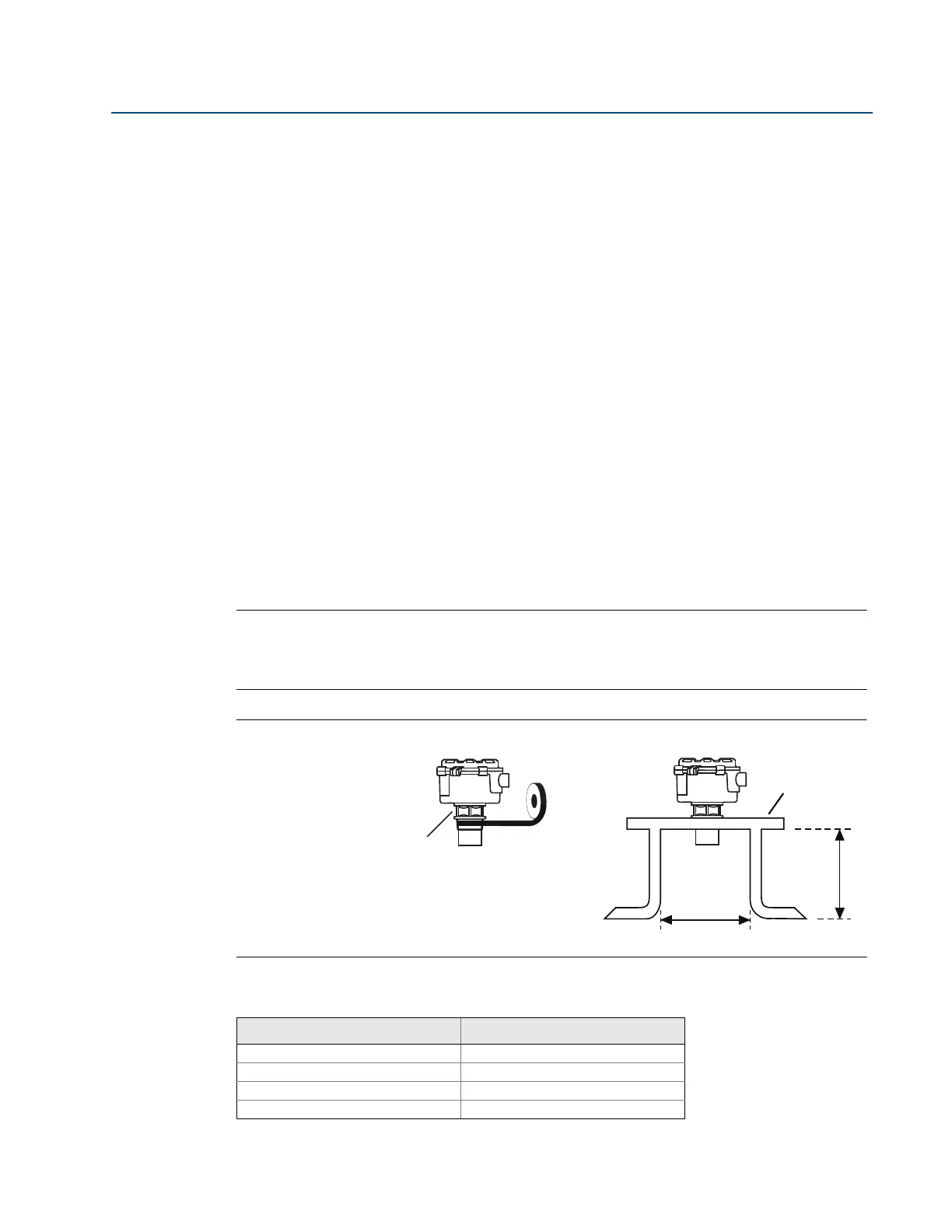
Installing in a tank with a nozzle or stand-off
Installation instructions
1. Use PTFE tape on the screw thread of the transmitter (Figure 3-4 on page 13).
2. If the tank has a flanged nozzle or stand-off:
a. Attach the transmitter to a non-metal instrument flange using the threaded
connection. Tighten to a torque of 1.5 lb-ft (2 N-m) using the transmitter’s hexagon.
b. The instrument (accessory) flanges supplied by Emerson Process Management are
manufactured from PVC and are a full face design. Care must be taken when installing
to a raised face mating flange on the tank or vessel to prevent distortion of the PVC
flange by over-tightening the bolts.
c. Ensure the gasket is sitting correctly on the nozzle/tank flange.
d. Lower the assembled transmitter and instrument flange onto the tank flange, and
secure with appropriate bolting to a suitable torque for the flanges.
If mating to a raised face flange (RF) on the tank nozzle or stand-off, tighten to a
maximum torque of 10 lb-ft (13.6 N-m).
3. If the tank has a threaded nozzle or stand-off:
a. Attach the transmitter to the nozzle/stand-off using the threaded connection.
b. Tighten to a torque of 1.5 lb-ft (2 N-m) using the transmitter’s hexagon.
Note
If the transmitter face does not protrude into the vessel, note the dimensions in Tabl e 3-1 for
Figure 3-4, and always ensure that the nozzle/vessel weld is smooth and free from internal weld
beads or other projections.
Figure 3-4. Mounting the Transmitter using a Nozzle/Stand-off
Table 3-1. Nozzle diameter size (D) and maximum length (L)
Nozzle Diameter Size (D) Maximum Nozzle Length (L)
DN50 (2 in.) 4 in. (100 mm)
DN80 (3 in.) 6.3 in. (160 mm)
DN100 (4 in.) 6.3 in. (160 mm)
DN125 (5 in.) 11.8 in. (300 mm)
PTFE
L
D
Tighten to a torque of 1.5 lbf.ft
(2 Nm) using the hexagon. Do
not use the housing to tighten
Use non-metallic
fitting / flange

 Loading...