14 General description CG Drives & Automation 01-7318-01r1
2.2 Emotron single drive cabinet concept
2.2.1 FDUL/VFXR/FDUG/VFXG
(single drive) applications
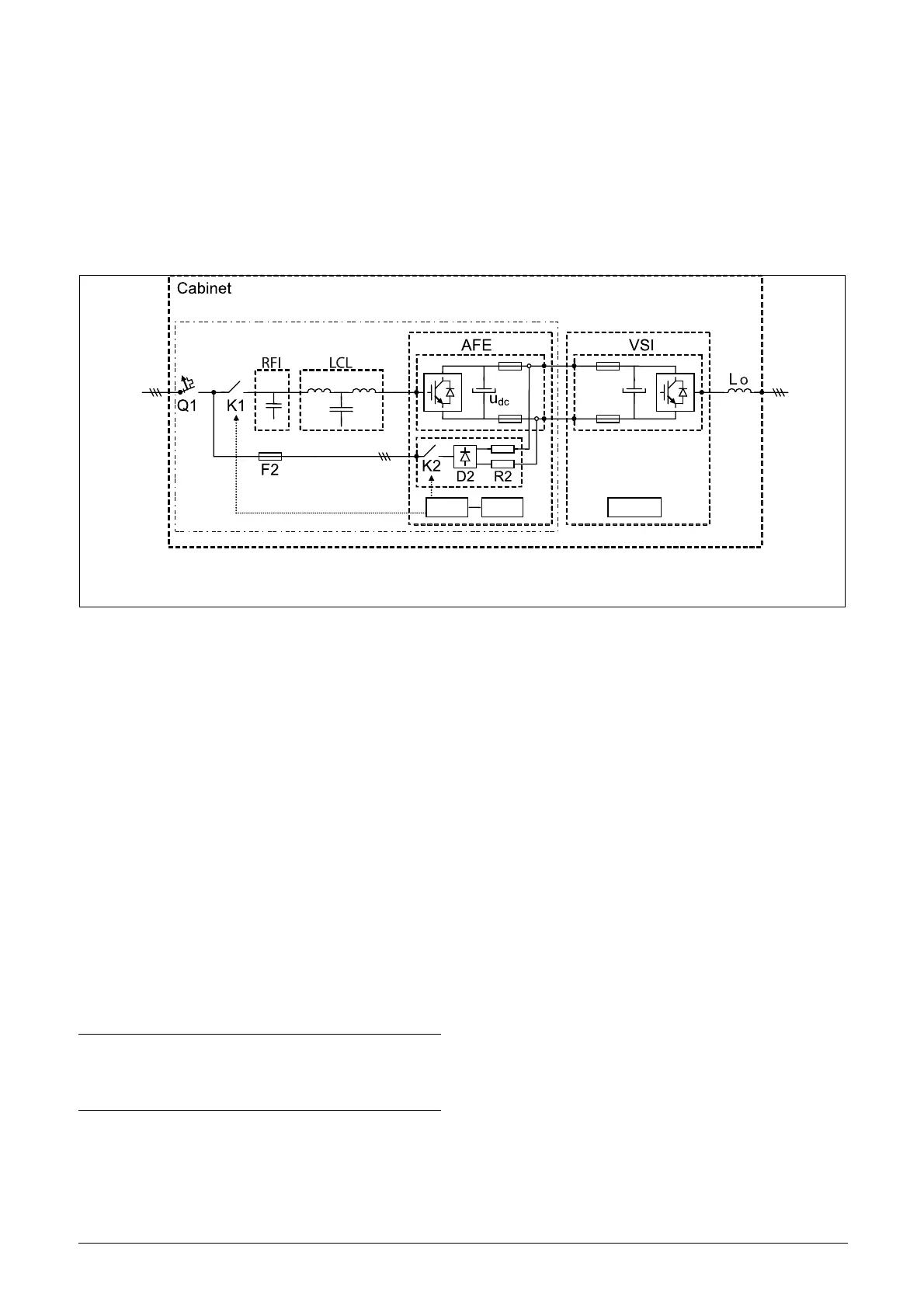
The Emotron low harmonic and regenerative AC drive i.e.
FDUL/VFXR/FDUG/VFXG is comprised by an AFR or
AFG unit i.e. AFE and filters and a VSI, i.e. Emotron VFX
or FDU. The concept is designed as a cabinet solution, see
Figure 6.
Fig. 6 Single drive in cabinet
where
• Cabinet - IP54 cabinet with door fans
• Q1 - Main switch *
• K1 - Main contactor *
•RFI - EMC filter
•LCL - LCL filter
• F2 - MCB (Miniature circuit breaker) for pre-charge
circuit
• AFE - Emotron AFE module with 24V standby supply
board, voltage measurement board (optional), brake
chopper switch (optional) and integrated pre-charge
circuit (K2,D2,R2)
• AFR/AFG - Emotron AFE and filters
• VSI - DC-voltage fed VSI module, i.e. Emotron VFX or
FDU
• CB - Control board
• SBS - Standby supply board
• Lo - Output coil
* For larger units, Q1 Main switch and K1 Main contact are
replaced by Q1 Motorized circuit breaker.
2.2.2 Common DC-bus applications
For common DC-bus applications, the cabinet will contain
only the AFR/AFG part of Figure 6, i.e. all except the VSI &
Lo.
AFR/AFG
CB
CB
SBS
AFR/AFG = AFE + LCL
FDUL/VFXR = AFR + VSI (FDU/VFX)
FDUG/VFXG = AFG + VSI (FDU/VFX)
NOTE:
For AFG/FDUG/VFXG, supply voltage measurement
board (SVMB) is mandatory. It is mounted and
connected internally to K2.

 Loading...