36 FDUL/VFXR/FDUG/VFXG/AFR/AFG Main features CG Drives & Automation, 01-7318-01r1
7.3 Automatic power supply
parameter detection
The AFR/AFG can automatically detect power supply
parameters voltage [O11], frequency [O12] and phase
sequence [O14] by separately activated function either
manually [O15] or automatically at every power up [O16].
The power supply parameters are detected by running a
network measurement routine. See chapter AFE Option
[O00] for detailed information about AFR/AFG
parameters.
7.4 Power supply
synchronisation
The AFR/AFG synchronises to the power supply when
starting by making test measurement. Synchronisation
during operation is handled via the U
dc
[O30], Q [O40]
and frequency [O50] controllers. See chapter AFE Option
[O00] for detailed information about AFR/AFG
parameters.
Synchronisation methods
• Standard sync (Default), extended sync routine.
This routine also verifies supply network. Takes approx.
50 ms.
• Voltage sync, i.e. via supply voltage measurement.
• Fast sync (fast measurement).
Fast sync method can be enabled via a service menu. Voltage
sync requires supply voltage measurement option and is
enabled via [O25].
7.5 Start command
The AFR/AFG can be started from digital I/O, control
panel (CP) or via serial communication options. Typically
the AFR/AFG is started via digital I/O either automatically
at power up or by the VSI when the VSI have a run
command.
In order to avoid unnecessary losses it is preferred only to
run the AFR/AFG when needed, i.e. when the VSI has a run
command. Fig. 20, page 26.
7.6 Start on regeneration
demand
The AFR/AFG can be started on regeneration demand
[O22], i.e. when the DC-link voltage increases due to
generated power from the VSIs. In motoring operation the
AFR/AFG modulation is deactivated and the free wheeling
diodes operates as a DFE and in regenerating operation the
AFR/AFG is activated and regenerates the energy back to
the supply.
Regeneration start/stop operation
• The AFR/AFG will start (DFE stop) when DC-link
voltage rises due to energy flow from load towards DC-
link.
• The AFR/AFG will stop (DFE start) when energy flow
from supply is positive (into the AFR/AFG) during stop
delay time [O23].
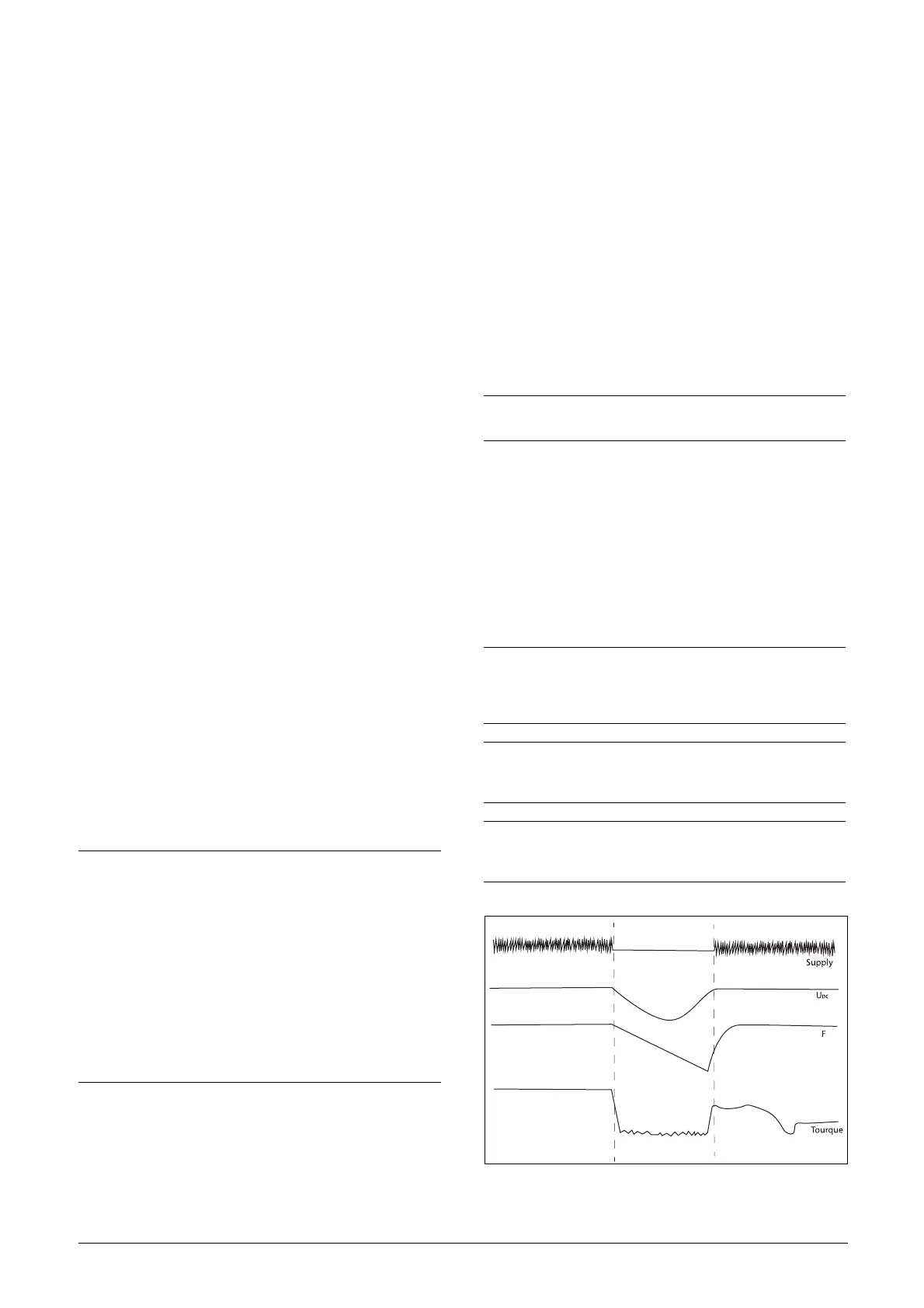
7.7 Under voltage ride through
for AFR/FDUL/VFXR
AFR/FDUL/VFXR running with voltage measurement
board, can withstand momentary power dips. The time to
which the system (drive) can stay alive depends on the
inertia of the application (load). If the system stays alive
based on the energy stored in the inertia, the system (AFR/
FDUL/VFXR) can continue its operation smoothly on
returning of the supply.
Fig. 29 Under voltage override
NOTE:
To protect AFE against damage an internal protection
has been added so that it does not allow AFE to start if
DC-link is already loaded. Sending start command
generates ''Start_Denied'' warning if there exists load on
DC-link. It is based on current measurement of AFR/
AFG.
If required, customer can turn this protection off with
the help of service/commissioning engineer.
If starting is required with loaded DC-link then it is
recommended to use voltage measurement board
(bypass/sync) option for starting/synchronization of
AFE.
NOTE:
Requires supply voltage measurement.
NOTE: During the momentary dip, AFR/FDUL/VFXR unit
will not be able to maintain THDI below 5%. However on
returning the supply and during smooth operation the
low harmonic or low THDI operation will be restored.
NOTE: For staying alive, corresponding settings must be
done on the VSI control board. Contact your local
supplier for assistance.
NOTE: For under voltage ride through function of AFR/
FDUL/VFXR, menus [O25] and [O51] must be set to
'Sensor' and [O24] must be set 'ON'.

 Loading...