CG Drives & Automation 01-7318-01r1 Troubleshooting, Diagnoses and Maintenance 147
12. Troubleshooting, Diagnoses and Maintenance
12.1 Trips, warnings and limits
In order to protect the AFR/AFG or VSI the principal
operating variables are continuously monitored by the
system. If one of these variables exceeds the safety limit an
error/warning message is displayed. In order to avoid any
possibly dangerous situations, the inverter sets itself into a
stop Mode called Trip and the cause of the trip is shown in
the display.
“Trip”
• The AFR/AFG/VSI stops immediately.
• The Trip relay or output is active (if selected).
• The Trip LED is on.
• The accompanying trip message is displayed.
• The “TRP” status indication is displayed (area D of the
display).
Apart from the TRIP indicators there are two more
indicators to show that the inverter is in an “abnormal”
situation.
“Warning”
• The AFR/AFG/VSI is close to a trip limit.
• The Warning relay or output is active (if selected).
• The Trip LED is flashing.
• The accompanying warning message is displayed in win-
dow [722] Warning.
• One of the warning indications is displayed (area F of
the display).
“Limits”
• The AFR/AFG/VSI is limiting torque and/or frequency
to avoid a trip.
• The Limit relay or output is active (if selected).
• The Trip LED is flashing.
• One of the Limit status indications is displayed (area D
of the display).
* Refer to Table 29 regarding which Desat or Power Fault is
triggered.
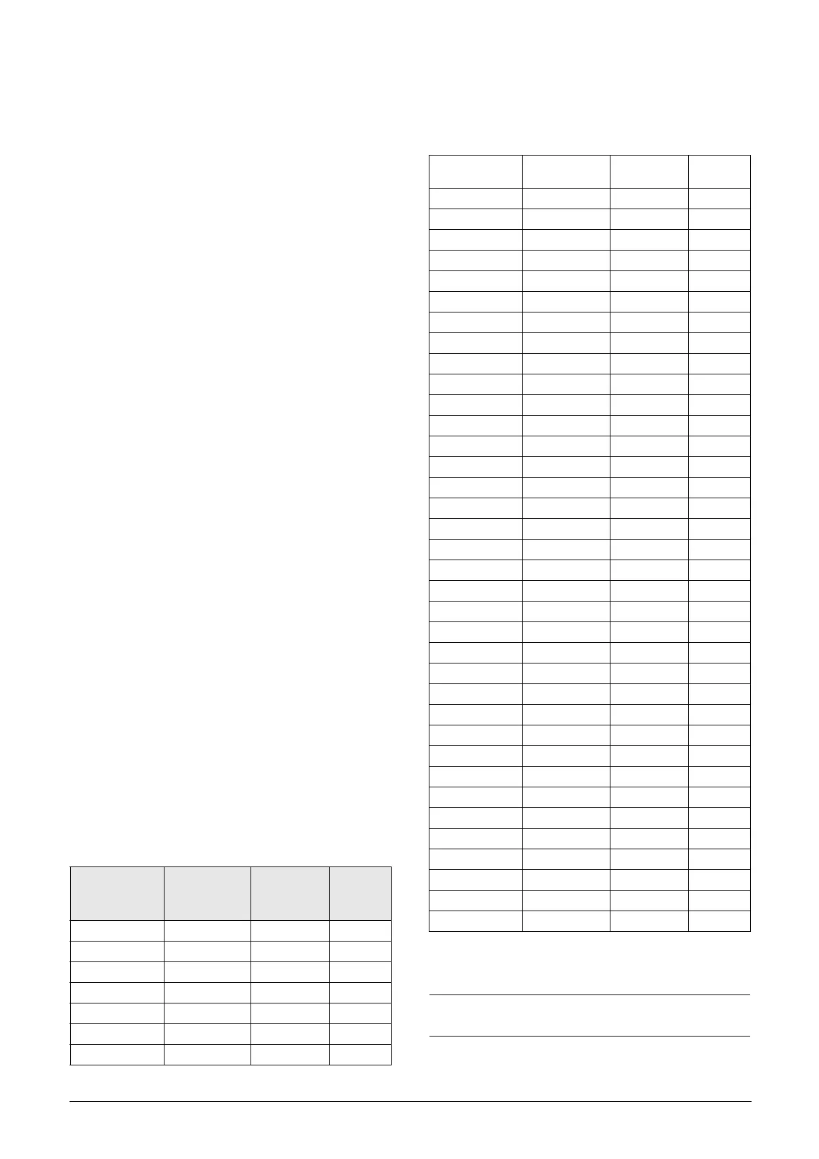
Table 28 List of trips and warnings
Trip/Warning
messages
Selections
Trip
(Normal/
Soft)
Warning
indicators
(Area D)
Ext trip Via DigIn Normal/Soft
Comm error Trip/Off/Warn Normal/Soft
Over temp On Normal OT
Over curr F On Normal
Over volt G On Normal
Over volt On Normal
Under voltage On Normal LV
LC Level
Trip/Off/Warn
Via DigIn
Normal/Soft LCL
Desat ### * On Normal
DClink error On Normal
Power Fault On Normal
PF #### * On Normal
Ovolt m cut On Normal
Supply error On Normal
Sup Chk Err On Normal
Sync error On Normal
AutoID error On Normal
Sup F Err On Normal
Sup U Err On Normal
Sensor Err On Normal
GCP 3U> On/Off Normal
GCP 3U>> On/Off Normal
GCP 3U< On/Off Normal
GCP 3U<< On/Off Normal
CGP U+> On/Off Normal
CGP U+< On/Off Normal
CGP U-> On/Off Normal
CGP U0> On/Off Normal
CGP Umean> On/Off Normal
CGP Umean< On/Off Normal
GCP U(Q<0)< On/Off Normal
GCP F> On/Off Normal
GCP F>> On/Off Normal
GCP F< On/Off Normal
GCP F<< On/Off Normal
GCP ROCOF On/Off Normal
UVRT On/Off Normal
OVRT On/Off Normal
Passive AID On/Off Normal
Active AID On/Off Normal
Resistor Err On/Off Normal
Open CB On/Off Normal
Rect I Error Off/Warn
PLL Not Lock Off/Warn
NOTE: For VSI refer to the Instruction manual for
Emotron FDU/VFX.
Table 28 List of trips and warnings

 Loading...