CG Drives & Automation, 01-7318-01r1 FDUL/VFXR/FDUG/VFXG/AFR/AFG Main features 35
7. FDUL/VFXR/FDUG/
VFXG/AFR/AFG
Main
features
This chapter contains descriptions of the main features of
the AFR/AFG drive.
7.1 Autoreset at trip
For several non-critical application-related failure
conditions, it is possible to automatically generate a reset
command to overcome the fault condition. The selection
can be made in menu [250]. In this menu the maximum
number of automatically generated restarts allowed can be
set, see menu [251], after this the AC drive will stay in fault
condition because external assistance is required.
Example
The motor is protected by an internal protection for thermal
overload. When this protection is activated, the AC drive
should wait until the motor is cooled down enough before
resuming normal operation. When this problem occurs
three times in a short period of time, external assistance is
required.
The following settings should be applied:
• Insert maximum number of restarts; set menu [251] to
3.
• Activate Over temp to be automatically reset; set menu
[252] to 300 s.
• Set relay 2, menu [552] to “AutoRst Trip”; a signal will
be available when the maximum number of restarts is
reached and the AC drive stays in fault condition.
• The reset input must be constantly activated.
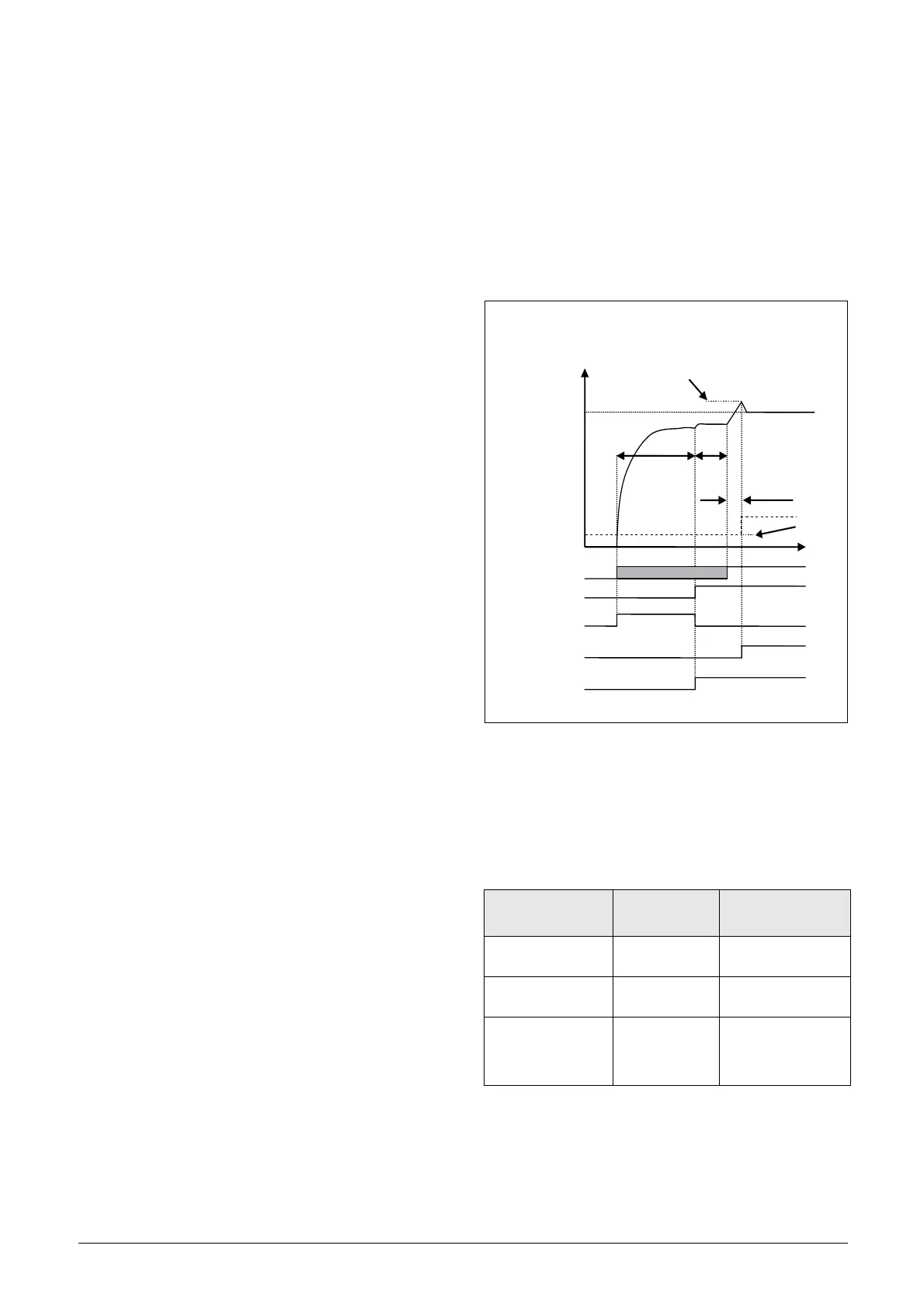
7.2 Power-up and DC-link
charging
Power up and charge control of the Emotron AFR/AFG and
DC-link (U
dc
) is handled via the dedicated control board
(CB) relays 1 and 3, where Charge contactor (K2) control is
fixed to CB Relay1 and Main contactor (K1) is fixed to CB
Relay3.
Typical charge time is 3-5 s and an additional delay after K1
activation of 1s is added before Run (or Auto ID) command
is acknowledged.
Fig. 28 DC-link voltage (U
dc
) charge control.
Signal Running OK, i.e. U
dc
under control can be signalled
via digital output or CB Relay2 selection “UDC_Ok”.
If Auto ID mode[O16] is used an additional delay of 1s is
inserted before Run command is acknowledged.
Table 11 I/O connection for AFR/AFG charge operation
AFR/AFG I/O
Contactor
K1/K2
Comment
Re1=’Charge
contactor’ {NC/NO}
K2.A1 (coil/ctrl)
Re3=’Main
contactor’ {NO}
K1.A1 (coil/ctrl)
DI3=’Enable’ K1.NO (aux)
Enable AFR/AFG only
if K1 OK. Preferably
used also for “Emer-
gency Stop”input.
Udc
ref
Udc
1s 3-5s
Udc PI
CB Re 1: Charge (K2)
CB Re 2: Option (OK)
CB Re 3: Main (K1)
CB DI1: Run
CB DI1: Enable
(1 +[O37])*[O31]
[O35]
[O36]

 Loading...