CG Drives & Automation 01-7318-01r1 Functional description 83
Keyboard reference mode [369]
This parameter sets how the reference value [310] is edited.
11.6 I/Os and Virtual
Connections [500]
Main menu with all the settings of the standard inputs and
outputs of the AFR/AFG drive.
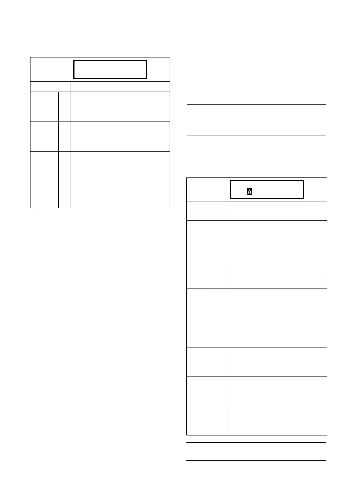
11.6.1 Analogue Inputs [510]
Submenu with all settings for the analogue inputs.
AnIn1 Function [511]
Sets the function for Analogue input 1. Scale and range are
defined by AnIn1 Advanced settings [513].
Default: MotPot
Normal 0
The reference value is edited as a normal
parameter (the new reference value is
activated when Enter is pressed after the
value has been changed).
MotPot 1
The reference value is edited using the
motor potentiometer function (the new
reference value is activated directly when
the key + or - is pressed).
MotPot+ 2
This selection makes it possible to update
the reference in “[310]” directly from the
[100]-menu. Pressing +/- in the [100]-
menu changes the menu to [310] and
there you can continue to press +/- to
update the reference. When no key has
been pressed for a second the menu
returns to [100] automatically.
369 Key Ref Mode
Stp MotPot
NOTE:
Analogue inputs [51x] can be used for voltage
measurement using voltage measurement board (sync/
bypass) option.
Default: Process Ref
Off 0 Input is not active
Max Torque 2 The input acts as an upper torque limit.
Process Val 3
The input value equals the actual process
value (feedback) and is compared to the
reference signal (set point) by the PID
controller, or can be used to display and
view the actual process value.
Process
Ref
4
Reference value is set for control in
process units, see Process Source [321]
and Process Unit [322].
Ux 7
x-axis (cartesian coordinate) supply
voltage measurement output signal from
supply voltage measurement board
(SVMB) to control board analogue input.
Uy 8
y-axis (cartesian coordinate) supply
voltage measurement output signal from
supply voltage measurement board
(SVMB) to control board analogue input.
U(L1) 9
Supply phase L1 voltage measurement
output signal from supply voltage
measurement board (SVMB) to control
board analogue input.
U(L2) 10
Supply phase L2 voltage measurement
output signal from supply voltage
measurement board (SVMB) to control
board analogue input.
U(L3) 11
Supply phase L3 voltage measurement
output signal from supply voltage
measurement board (SVMB) to control
board analogue input.
NOTE: When AnInX Func=Off, the connected signal
will still be available for Comparators [610].
511 AnIn1 Fc
Stp Process Ref

 Loading...