24 Control connections CG Drives & Automation 01-7318--01r1
5.2 Terminal connections for
AFR/AFG
The terminal strip for connecting the control signals is
accessible after opening the front door.
The table describes the default functions for the signals. The
inputs and outputs are programmable for other functions as
described in chapter 11. page 69. For signal specifications
refer to chapter 14. page 159.
For VSI, refer to instruction manual for Emotron FDU or
VFX.
NOTE:
The maximum total combined current available for
outputs 11, 20 and 21 is 100 mA. Supply voltage
measurement board (SVMB) when connected (for
example in AFG) takes 50 mA out of that total available
(100 mA) current.
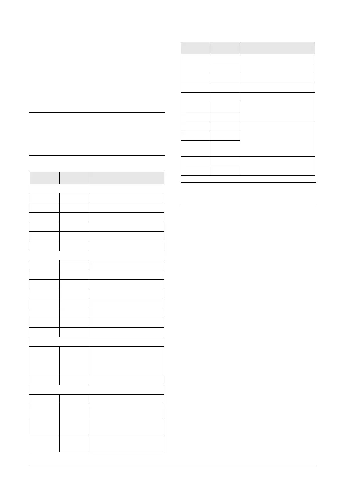
Table 7 Control signals for AFR/AFG
Terminal Name Function (Default)
Outputs
1 +10 V +10 VDC supply voltage
6 -10 V -10 VDC supply voltage
7 Common Signal ground
11 +24 V +24 VDC supply voltage
12 Common Signal ground
15 Common Signal ground
Digital inputs
8 DigIn 1 RunL (reverse)
9 DigIn 2 RunR (forward)
10 DigIn 3 Enable
16 DigIn 4 Off
17 DigIn 5 Off
18 DigIn 6 Off
19 DigIn 7 Off
22 DigIn 8 RESET
Digital outputs
20 DigOut 1
LY (logic Y)
Active when AFE not running or
DC-link voltage has not reached
reference value
21 DigOut 2 LZ (Trip pulse of 1s)
Analogue inputs
2AnIn 1Process Ref
3AnIn 2
AFR: Off
AFG: U(L1)
4AnIn 3
AFR: Off
AFG: U(L2)
5AnIn 4
AFR: Off
AFG: U(L3)
Analogue outputs
13 AnOut 1 0 to nominal current
14 AnOut 2 0 to max torque
Relay outputs
31 N/C 1
Relay 1 output
Dedicated for Charge
contactor K2.
32 COM 1
33 N/O 1
41 N/C 2 Relay 2
LY (logic Y)
Active when AFE not running or
DC-link voltage has not reached
reference value
42 COM 2
43 N/O 2
51 COM 3
Relay 3 output
Dedicated for Main contactor K1
52 N/O 3
NOTE:
N/C is opened when the relay is active and N/O is closed
when the relay is active.
Table 7 Control signals for AFR/AFG
Terminal Name Function (Default)

 Loading...