CG Drives & Automation 01-7318-01r1 General description 15
2.3 Emotron AFR/AFG concept
Emotron also offers only AFR/AFG solution for the
applications where complete FDUL/VFXR/FDUG/VFXG
drive train is not required. In this concept, the DC power
load/source is connected to the DC-terminals of AFR/AFG.
AFR/AFG consists of AFE power electronic module and
LCL filters as main components along with other necessary
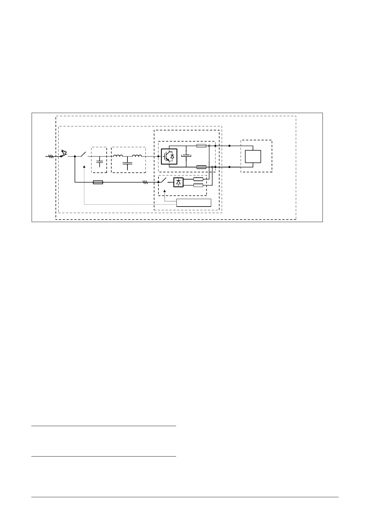
components. AFR/AFG concept is shown in Figure 7.
Fig. 7 AFR/AFG concept
where
• Cabinet - outer cabinet (for example IP54)
• Q1 - Main switch *
• K1 - Main contactor *
•RFI - EMC filter
•LCL - LCL filter
• F2 - MCB (Miniature circuit breaker) for pre-charge
circuit
• AFE - Emotron AFE module with 24V standby supply
board, voltage measurement board (optional for AFR
and mandatory for AFG), optional brake chopper switch
and integrated pre-charge circuit (K2, D2, R2)
• AFR/AFG - Emotron AFE and filters
• DC source/load - External DC power source or load
based on the application.
• CB - Control board
• SBS - Standby supply board
* For larger units, Q1 Main switch and K1 Main contact
are replaced by Q1 Motorized circuit breaker.
Cabinet
DC
source/load
Q1 K1
F2
RFI L2
AFR/AFG
AFE
U
dc
K2
D2 R2
CB & PPU
C
DC+
DC-
NOTE:
For AFG/FDUG/VFXG, supply voltage measurement
board (SVMB) is mandatory. It is mounted and
connected internally to K2.

 Loading...