CG Drives & Automation 01-7318-01r1 Functional description 97
11.7 Logical Functions and
Timers [600]
With the Comparators, Logic Functions and Timers,
conditional signals can be programmed for control or
signalling features. This gives you the ability to compare
different signals and values in order to generate monitoring/
controlling features.
11.7.1 Comparators [610]
The comparators available make it possible to monitor
different internal signals and values, and visualize via digital
relay outputs, when a specific value or status is reached or
established.
Analogue comparators [611] - [614]
There are 4 analogue comparators that compare any
available analogue value (including the analogue reference
inputs) with two adjustable levels. The two levels available
are Level HI and Level LO. There are two analogue
comparator types selectable, an analogue comparator with
hysteresis and an analogue window comparator.
The analogue hysteresis type comparator uses the two
available levels to create a hysteresis for the comparator
between setting and resetting the output. This function gives
a clear difference in switching levels, which lets the process
adapt until a certain action is started. With such a hysteresis,
even an unstable analogue signal can be monitored without
getting a nervous comparator output signal. Another feature
is the possibility to get a fixed indication that a certain level
has been passed. The comparator can latch by setting Level
LO to a higher value than Level HI.
The analogue window comparator uses the two available
levels to define the window in which the analogue value
should be within for setting the comparator output.
The input analogue value of the comparator can also be
selected as bipolar, i.e. treated as signed value or
unipolar, i.e. treated as absolute value.
Refer to Fig. 79, page 101 where these functions are
illustrated.
Digital comparators [615]
There are 4 digital comparators that compare any available
digital signal.
The output signals of these comparators can be logically tied
together to yield a logical output signal.
All the output signals can be programmed to the digital or
relay outputs or used as a source for the virtual connections
[560].
CA1 Setup [611]
Analogue comparator 1, parameter group.
Analogue Comparator 1, Value [6111]
Selection of the analogue value for Analogue Comparator 1
(CA1).
Analogue comparator 1 compares the selectable analogue
value in menu [6111] with the constant Level HI in menu
[6112] and constant Level LO in menu [6113]. If Bipolar
type[6115] input signal is selected then the comparison is
made with sign otherwise if unipolar selected then
comparison is made with absolute values.
For Hysteresis comparator type [6114], when the value
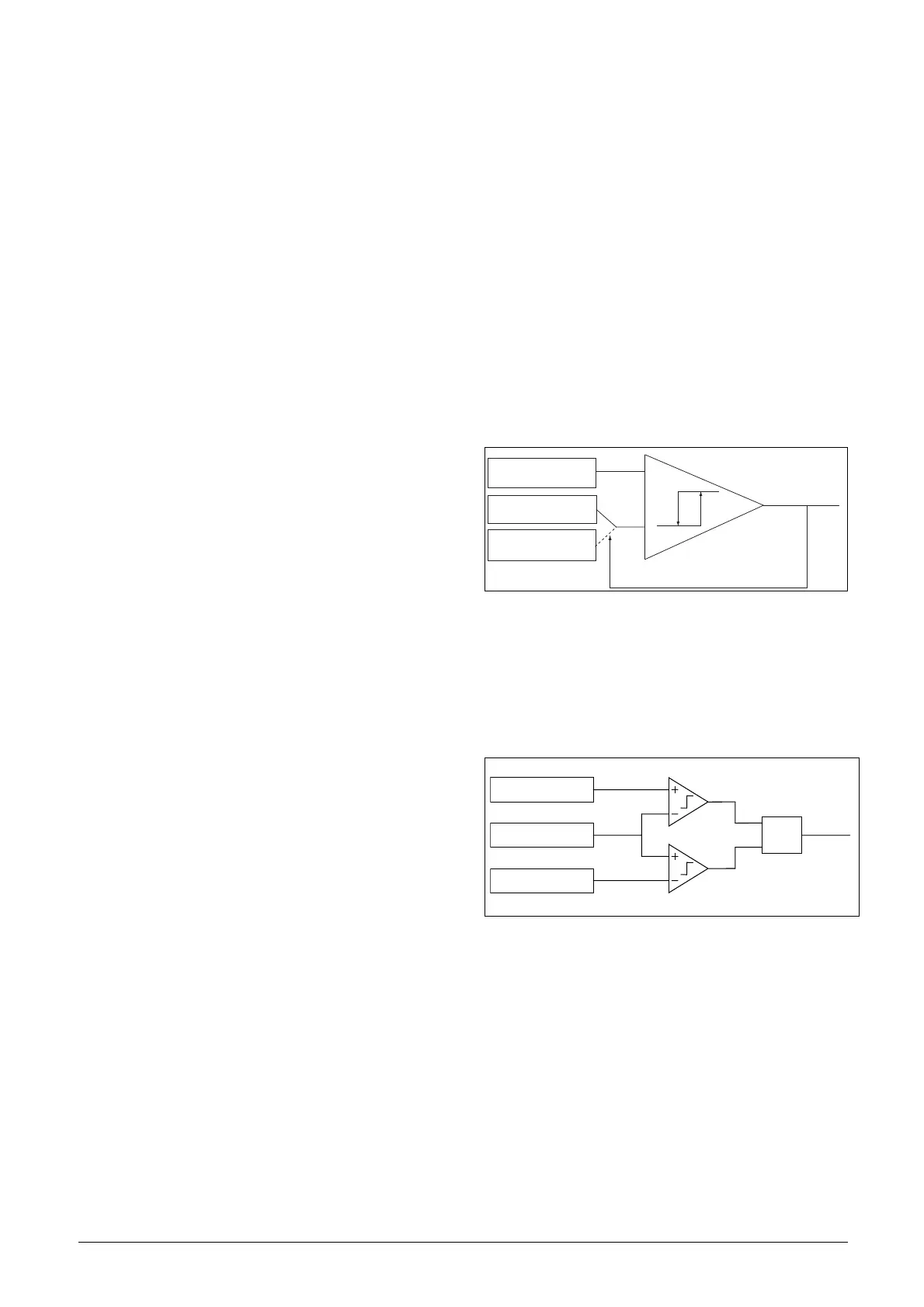
exceeds the upper limit level high, the output signal CA1 is
set high and !A1 low, see Fig. 75. When the value decreases
below the lower limit, the output signal CA1 is set low and
!A1 high.
Fig. 75 Analogue comparator type Hysteresiss
For Window comparator type [6114], when the value is
between the lower and upper levels, the output signal value
CA1 is set high and !A1 low, see Fig. 78, page 99. When the
value is outside the band of lower and upper levels, the
output CA1 is set low and !A1 high.
Fig. 76 Analogue comparator type “Window”
(NG_06-F125)
0
1
Analogue value:
Menu [6111]
Adjustable Level HI.
Menu [6112]
Adjustable Level LO.
Menu [6113]
Level High[6112]
An Value [6111]
Level Low [6113]
AND
Signal
CA1

 Loading...