CG Drives & Automation 01-7318-01r1 Control connections 25
5.3 Inputs configuration with
the switches
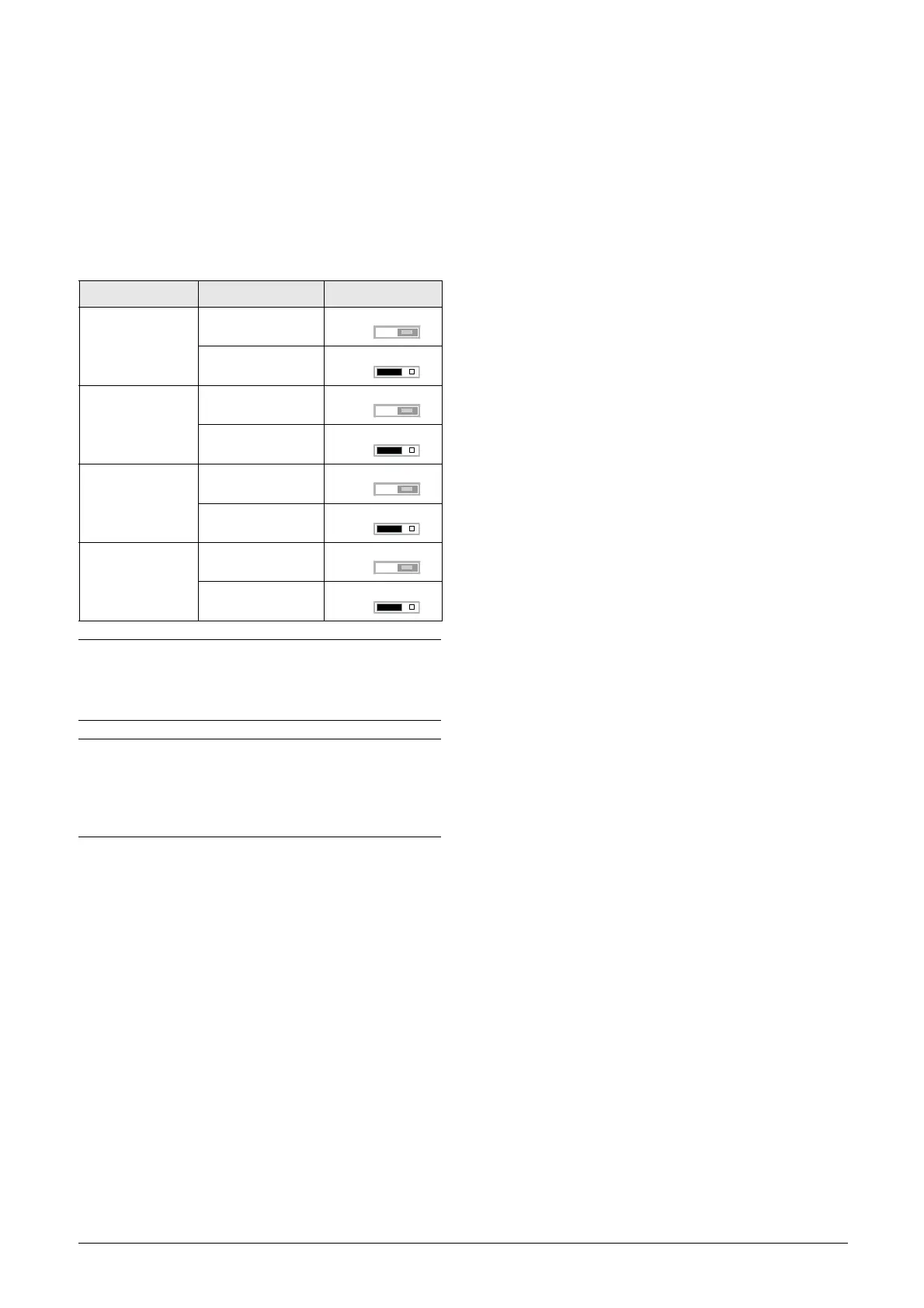
The switches S1 to S4 are used to set the input configuration
for the 4 analogue inputs AnIn1, AnIn2, AnIn3 and AnIn4
as described in Table 8.
The switches on the Control board are accessible after
opening the door and removing the PPU cover plate.
Table 8 Switch settings
Input Signal type Switch
AnIn1
Voltage
S1
Current (default)
S1
AnIn2
Voltage
S2
Current (default)
S2
AnIn3
Voltage
S3
Current (default)
S3
AnIn4
Voltage
S4
Current (default)
S4
NOTE:
Scaling and offset of AnIn1 - AnIn4 can be configured
using the software. See menus [512], [515], [518] and
[51B].
NOTE:
Switches for AnIn2 to AnIn4 must be in U (Voltage
position) when using Voltage measurement board.
Switches must be in I (Current) position if current source
is used for analogue input.
U
I
U
I
U
I

 Loading...