58 Operation via the Control Panel CG Drives & Automation 01-7318-01r1
9.4 Control panel with 4-line
display
This control panel with 4-line display is equipped with real
time clock function. This means that actual date and time
will be shown at e.g. a trip condition.
There is also an optional Control panel with Bluetooth
communication available. See chapter 13.6 Control panel
on page 156 for more information.
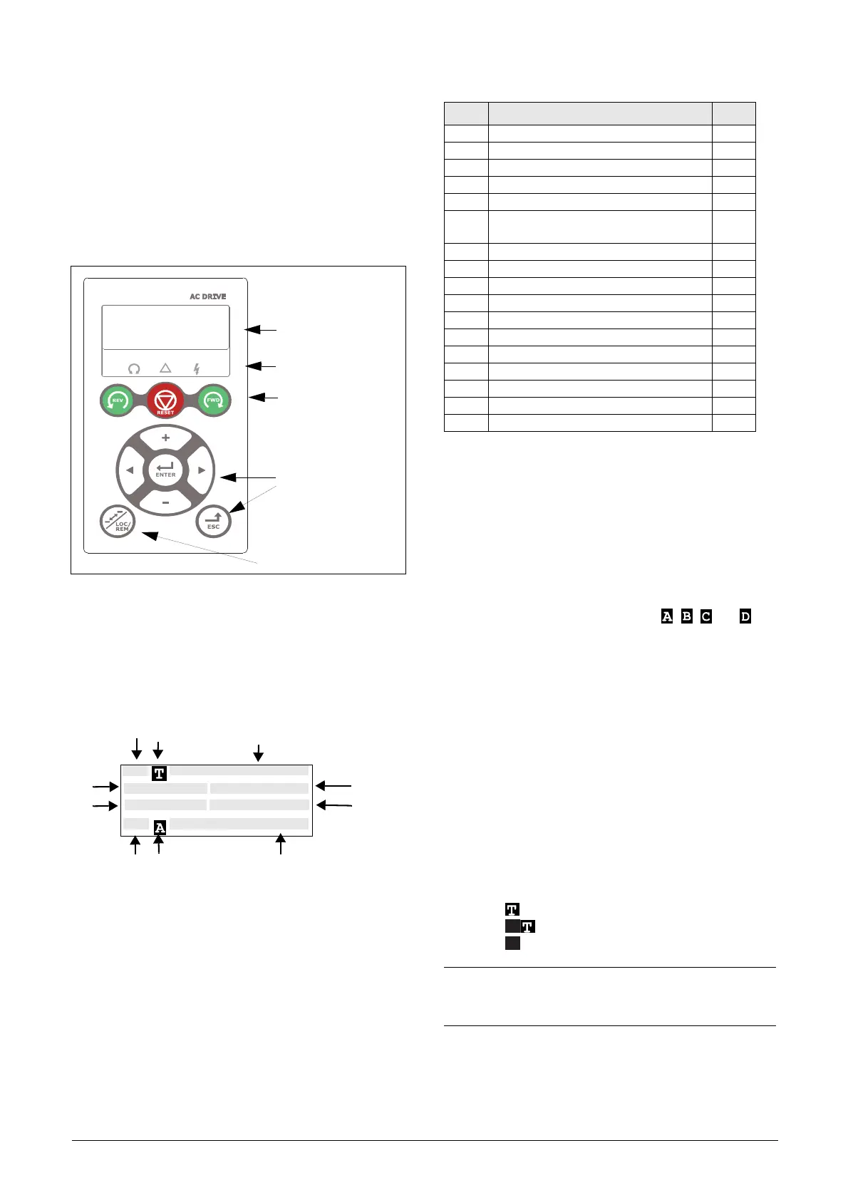
Fig. 60 Control panel with 4-line display, LEDs and Keys.
9.4.1 The display
The display is back lit and consists of 4 rows, each with
space for 20 characters. The display is divided into following
areas. The different areas in the display are described below:
Fig. 61 The display.
Area A: Shows the actual menu number (3 or 4 digits).
Area B: Menu name or heading (Except in menus 100+
mode), 8 characters field.
Area C: Edit Cursor if editing or heading in menu [100],
8 characters field.
Area D*: Shows the status of the AC drive (3 digits). The
following status indications are possible:
*) The status shown in Area D on the control panel can be
read via a fieldbus or serial communication, e.g. using
Modbus address No. 30053.
It is also possible to read all status indications, not just the
highest prioritized one, via a fieldbus or serial
communication, e.g. using Modbus address No. 30180 and
30182. This information is also shown in EmoSoftCom
PC-tool (optional), see menu “Area D status [72B]” of VSI
instruction.
Area E: Shows active parameter set: , , , or
[241].
Area F: Active control source.
Area G: Parameter value, shows the setting or selection in
the active menu, 12 characters field.
This area is empty at the 1st level and 2nd level
menu. This area also shows warnings and alarm
messages. In some situations this area could
indicate “+++” or ” - - -” see further
information in the Instruction manual.
Area H: Signal values shown in menu [100], 12 characters
field.
Area I: Preferred read-out value (chosen in menu [110])
Area J Shows if the menu is in the toggle loop and/or
the AC drive is set for Local operation.
= in Toggle loop
= in Local operation and Toggle loop
= Local operation
4 line
LEDs
Control Keys
Toggle Key
Function Keys
LCD display
100 1240rpm
Torque 0% 0.0Nm
Current 123.3A
Sby Key/Key
A
I
J
H
G
F
E
D
C
B
Digits Description Bit*
Stp AFE/VSI is stopped 0
Run AFE/VSI runs 1
Acc Acceleration 2
Dec Deceleration 3
Trp Tripped 4
SST
Operating Safe Stop, is flashing when
activated
5
VL Operating at voltage limit 6
SL Operating at speed limit 7
CL Operating at current limit 8
TL Operating at torque limit 9
OT Operating at temperature limit 10
I
2
t Active I
2
t protection 11
LV Operating at low voltage 12
Sby Operating from Standby power supply 13
LCL Operating with low cooling liquid level 14
Slp Sleep mode 15
SPS Spin start active 16
NOTE:
In area B and area C only 8 characters are available,
this means that some texts will be shortened.

 Loading...