30 Control connections CG Drives & Automation 01-7318--01r1
Example:
The relay output from a motor inverter which controls an
auxiliary relay can, at the moment of switching, form a
source of interference (emission) for a measurement signal
from, for example, a pressure sensor. Therefore it is advised
to separate wiring and screening to reduce disturbances.
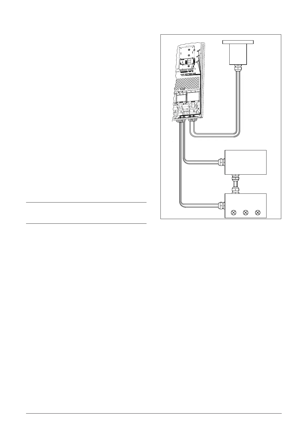
5.5.3 Screening
For all signal cables the best results are obtained if the
screening is connected to both ends: the VSI side and at the
source (e.g. PLC, or computer). See Fig. 35.
It is strongly recommended that the signal cables be allowed
to cross mains and motor cables at a 90° angle. Do not let
the signal cable go in parallel with the mains and motor
cable.
5.5.4 Single-ended or double-ended
connection?
In principle, the same measures applied to motor cables
must be applied to all control signal cables, in accordance
with the EMC-Directives.
For all signal cables as mentioned in section 5.5.2 the best
results are obtained if the screening is connected to both
ends. See Fig. 35.
Fig. 25 Electro Magnetic (EM) screening of control signal
cables.
5.5.5 Current signals ((0)4-20 mA)
A current signal like (0)4-20 mA is less sensitive to
disturbances than a 0-10 V signal, because it is connected to
an input which has a lower impedance (250 Ω) than a
voltage signal (20 kΩ). It is therefore strongly advised to use
current control signals if the cables are longer than a few
metres.
5.5.6 Twisted cables
Analogue and digital signals are less sensitive to interference
if the cables carrying them are “twisted”. This is certainly to
be recommended if screening cannot be used. By twisting
the wires the exposed areas are minimised. This means that
in the current circuit for any possible High Frequency (HF)
interference fields, no voltage can be induced. For a PLC it
is therefore important that the return wire remains in
proximity to the signal wire. It is important that the pair of
wires is fully twisted over 360°.
5.6 Connecting options
The option cards are connected by the optional connectors
X4 or X5 on the control board see Fig. 19, page 23 and
mounted above the control board. The inputs and outputs
of the option cards are connected in the same way as other
control signals.
NOTE:
Each installation must be examined carefully before
applying the proper EMC measurements.
External control
(e.g. in metal housing)

 Loading...