54 Operation via the Control Panel CG Drives & Automation 01-7318-01r1
9.3 Control panel with 2-line
display
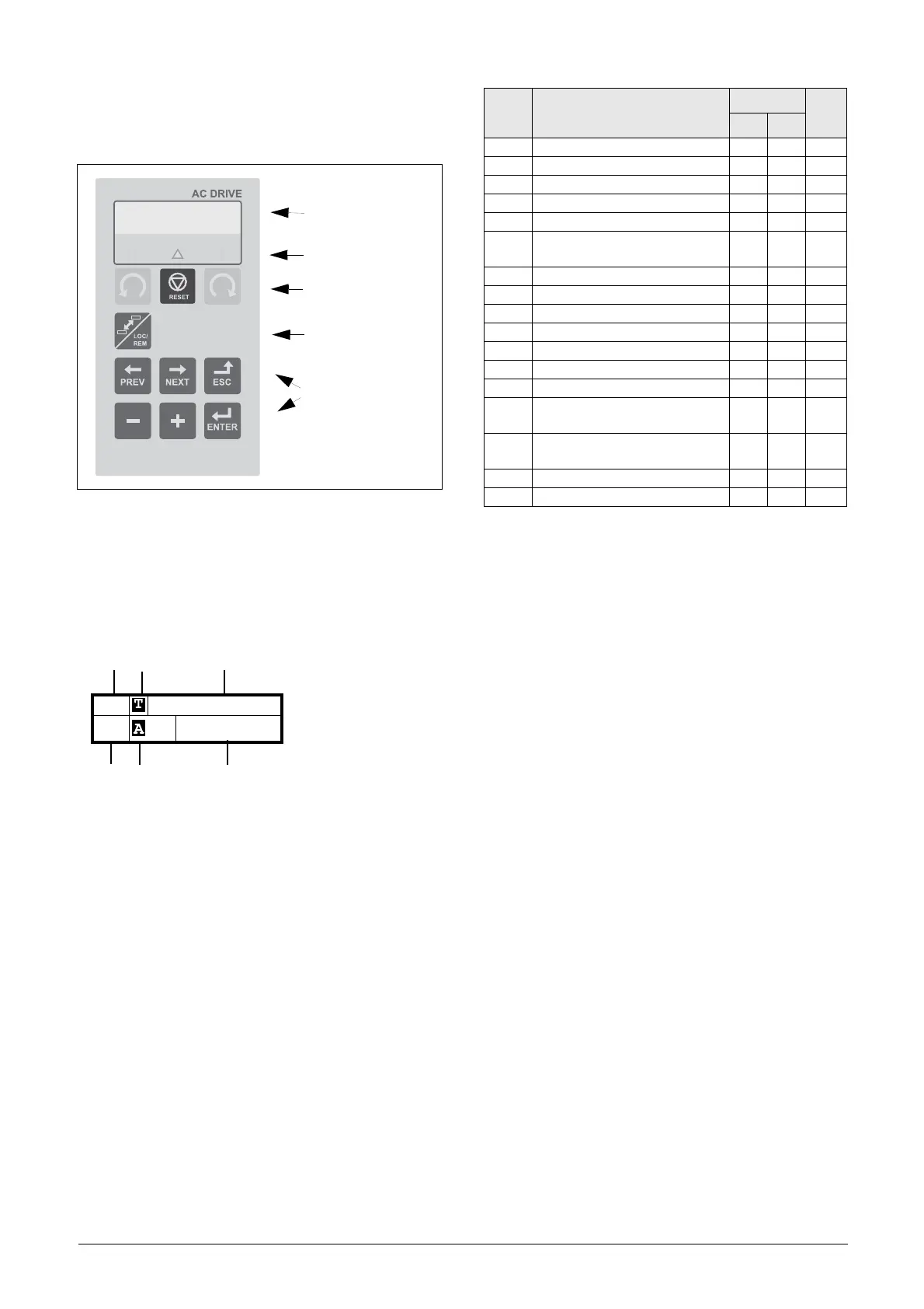
Fig. 52 Control panel
9.3.1 The display
The display is back lit and consists of 2 rows, each with
space for 16 characters. The display is divided into six areas.
The different areas in the display are described below:
Fig. 53 The display
Area A: Shows the actual menu number (3 or 4
digits).
Area B Shows if the menu is in the toggle loop or the
driveunit is set for Local operation.
Area C: Shows the heading of the active menu.
Area D: Shows the status of the driveunit (3 digits).
The following status indications are possible:
*) For a VSI the status shown in Area D on the control panel
can be read via a fieldbus or serial communication, e.g. using
Modbus address No. 30053.
It is also possible to read all status indications, not just the
highest prioritized one, via a fieldbus or serial
communication, e.g. using Modbus address No. 30180 and
30182. This information is also shown in EmoSoftCom
PC-tool (optional) see menu “Area D status [72B]” of VSI
instruction.
Area E: Shows active parameter set and if it is a motor
parameter.
Area F: Shows the setting or selection in the active menu.
This area is empty at the 1st level and 2nd level
menu. This area also shows warnings and alarm
messages. In some situations this area could
indicate +++ or - - - please see further
information in chapter 9.3.2 page 55.
LC Display
LEDs
Control Keys
Toggle Key
Function Keys
Digits Description
Shown in
Bit*
AFE VSI
Stp AFE/VSI is stopped X X 0
Run AFE/VSI runs X X 1
Acc Acceleration X 2
Dec Deceleration X 3
Trp Tripped X X 4
SST
Operating Safe Stop, is flashing
when activated
X5
VL Operating at voltage limit X X 6
SL Operating at speed limit X 7
CL Operating at current limit X X 8
TL Operating at torque limit X X 9
OT Operating at temperature limit X X 10
I
2
tActive I
2
t protection X X 11
LV Operating at low voltage X X 12
Sby
Operating from Standby power
supply
XX13
LCL
Operating with low cooling liquid
level
XX14
Slp Sleep mode X X 15
SPS Spin start active X 16

 Loading...