CG Drives & Automation 01-7318-01r1 Operation via the Control Panel 55
Fig. 54 Example 1st level menu
Fig. 55 Example 2nd level menu
Fig. 56 Example 3d level menu
Fig. 57 Example 4th level menu
9.3.2 Indications on the display
The display can indicate +++ or - - - if a parameter is out of
range. In the VSI there are parameters which are dependent
on other parameters. For example, if the speed reference is
500 and the maximum speed value is set to a value below
500, this will be indicated with +++ on the display. If the
minimum speed value is set over 500, - - - is displayed.
9.3.3 LED indicators
The symbols on the control panel have the following
functions:
Fig. 58 LED indications
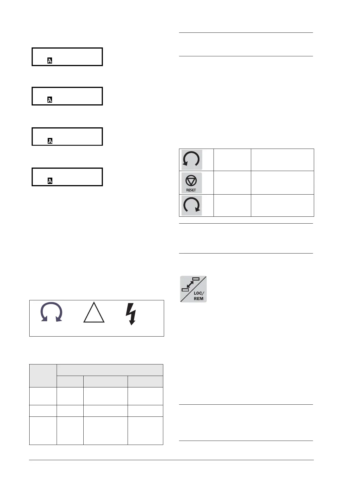
9.3.4 Control keys
The control keys are used to give the Run, Stop or Reset
commands directly. As default these keys are disabled, set for
remote control. Activate the control keys by selecting
Keyboard in the menus Ref Control [214] and Reset Ctrl
[216].
If the Enable function is programmed on one of the digital
inputs, this input must be active to allow Run/Stop
commands from the control panel
.
9.3.5 The Toggle and Loc/Rem Key
This key has two functions: Toggle and
switching between Loc/Rem function.
Press one second to use the toggle function
Press and hold the toggle key for more than
five seconds to switch between Local and Remote function,
depending on the settings in [2171] and [2172].
When editing values, the toggle key can be used to change
the sign of the value, see section 9.7, page 63.
Toggle function
Using the toggle function makes it possible to easily step
through selected menus in a loop. The toggle loop can
contain a maximum of ten menus. As default the toggle loop
contains the menus needed for Quick Setup. You can use the
toggle loop to create a quick-menu for the parameters that
are most importance to your specific application.
Table 13 LED indication
Symbol
Function
ON FLASHING OFF
POWER
(green)
Power on ---------------- Power off
TRIP (red) Tripped Warning/Limit No trip
RUN
(green)
Running
AC drive speed
increase/
decrease (VSI
only)
AFR/AFG/VSI
stopped
7311 Reset RunTm
Stp 00:00:00
Run
Green
Trip
Red
Power
Green
NOTE: If the control panel is built in, the back light of the
display has the same function as the Power LED in Table
13 (Blank panel LEDs).
Ta b l e 1 4 C o n t r o l k e y s
RUN L:
gives a start with
left rotation
STOP/RESET: stops or resets
RUN R:
gives a start with
right rotation
NOTE:
It is not possible to simultaneously activate the Run/
Stop commands from the keyboard and remotely from
the terminal strip (terminals 1-22).
NOTE:
Do not keep the Toggle key pressed for more than five
seconds without pressing either the +, - or Esc key, as
this may activate the Loc/Rem function of this key
instead. See menu [217].

 Loading...