84 Functional description CG Drives & Automation 01-7318-01r1
Adding analogue inputs
If more than one analogue input is set to the same function,
the values of the inputs can be added together. In the
following examples we assume that Process Source [321] is
set to Speed.
Example 1: Add signals with different weight (fine tuning).
Signal on AnIn1 = 10 mA
Signal on AnIn2 = 5 mA
[511] AnIn1 Function = Process Ref.
[512] AnIn1 Setup = 4-20 mA
[5134] AnIn1 Function Min = Min (0 rpm)
[5136] AnIn1 Function Max = Max (1500 rpm)
[5138] AnIn1 Operation = Add+
[514] AnIn2 Function = Process Ref.
[515] AnIn2 Setup = 4-20 mA
[5164] AnIn2 Function Min = Min (0 rpm)
[5166] AnIn2 Function Max = User defined
[5167] AnIn2 Value Max = 300 rpm
[5168] AnIn2 Operation = Add+
Calculation:
AnIn1 = (10-4) / (20-4) x (1500-0) + 0 = 562.5 rpm
AnIn2 = (5-4) / (20-4) x (300-0) + 0 = 18.75 rpm
The actual process reference will be:
+562.5 + 18.75 = 581 rpm
Analogue Input Selection via Digital
Inputs:
When two different external Reference signals are used,
e.g. 4-20mA signal from control centre and a 0-10 V locally
mounted potentiometer, it is possible to switch between
these two different analogue input signals via a Digital Input
set to “AnIn Select”.
AnIn1 is 4-20 mA
AnIn2 is 0-10 V
DigIn3 is controlling the AnIn selection; HIGH is 4-20 mA,
LOW is 0-10 V
“[511] AnIn1 Fc” = Process Ref;
set AnIn1 as reference signal input
“[512] AnIn1 Setup” = 4-20mA;
set AnIn1 for a current reference signal
“[513A] AnIn1 Enabl” = DigIn;
set AnIn1 to be active when DigIn3 is HIGH
“[514] AnIn2 Fc” = Process Ref;
set AnIn2 as reference signal input
“[515] AnIn2 Setup” = 0-10V;
set AnIn2 for a voltage reference signal
“[516A] AnIn2 Enabl” = !DigIn;
set AnIn2 to be active when DigIn3 is LOW
“[523] DigIn3=AnIn”;
set DIgIn3 as input fot selection of AI reference
Subtracting analogue inputs
Example 2: Subtract two signals
Signal on AnIn1 = 8 V
Signal on AnIn2 = 4 V
[511] AnIn1 Function = Process Ref.
[512] AnIn1 Setup = 0-10 V
[5134] AnIn1 Function Min = Min (0 rpm)
[5136] AnIn1 Function Max = Max (1500 rpm)
[5138] AnIn1 Operation = Add+
[514] AnIn2 Function = Process Ref.
[515] AnIn2 Setup = 0-10 V
[5164] AnIn2 Function Min = Min (0 rpm)
[5166] AnIn2 Function Max = Max (1500 rpm)
[5168] AnIn2 Operation = Sub-
Calculation:
AnIn1 = (8-0) / (10-0) x (1500-0) + 0 = 1200 rpm
AnIn2 = (4-0) / (10-0) x (1500-0) + 0 = 600 rpm
The actual process reference will be:
+1200 - 600 = 600 rpm
AnIn1 Setup [512]
The analogue input setup is used to configure the analogue
input in accordance with the signal used that will be
connected to the analogue input. With this selection the
input can be determined as current (4-20 mA) or voltage
(0-10 V) controlled input. Other selections are available for
using a threshold (live zero), a bipolar input function, or a
user defined input range. With a bipolar input reference
signal, it is possible to control the motor in two directions.
See Fig. 69.
NOTE:
The selection of voltage or current input is done with
S1. When the switch is in voltage mode only the
voltage menu items are selectable. With the switch in
current mode only the current menu items are
selectable.
Default: User Bipol V
Dependent on Setting of switch S1
4–20mA 0
The current input has a fixed threshold
(Live Zero) of 4 mA and controls the full
range for the input signal. See Fig. 81.
0–20mA 1
Normal full current scale configuration of
the input that controls the full range for the
input signal. See Fig. 80.
User mA 2
The scale of the current controlled input,
that controls the full range for the input
signal. Can be defined by the advanced
AnIn Min and AnIn Max menus.
User Bipol
mA
3
Sets the input for a bipolar current input,
where the scale controls the range for the
input signal. Scale can be defined in
advanced menu AnIn Bipol.
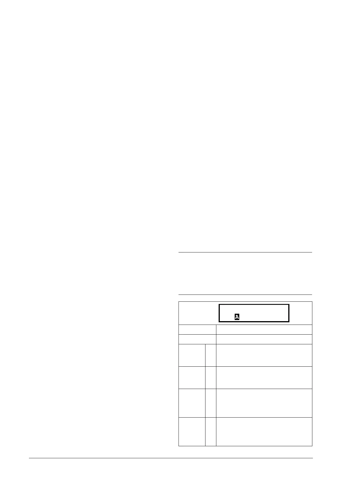
512 AnIn1 Setup
Stp User Bipol V

 Loading...