Emotron AB 01-4429-01r2 Options 155
13.4 I/O Board
The I/O option board 2.0 provides three extra relay outputs
and three extra digital inputs. The I/O Board works in com-
bination with the Pump/Fan Control, but can also be used
as a separate option. This option is described in a separate
manual.
13.5 Output coils
Output coils, which are supplied separately, are recom-
mended for lengths of screened motor cable longer than 100
m. Because of the fast switching of the motor voltage and
the capacitance of the motor cable both line to line and line
to earth screen, large switching currents can be generated
with long lengths of motor cable. Output coils prevent the
VSD from tripping and should be installed as closely as pos-
sible to the VSD.
13.6 Serial communication
and fieldbus
For communication with the VSD there are several option
boards for communication. There are different options for
Fieldbus communication and one serial communication
option with RS232 or RS485 interface which has galvanic
isolation.
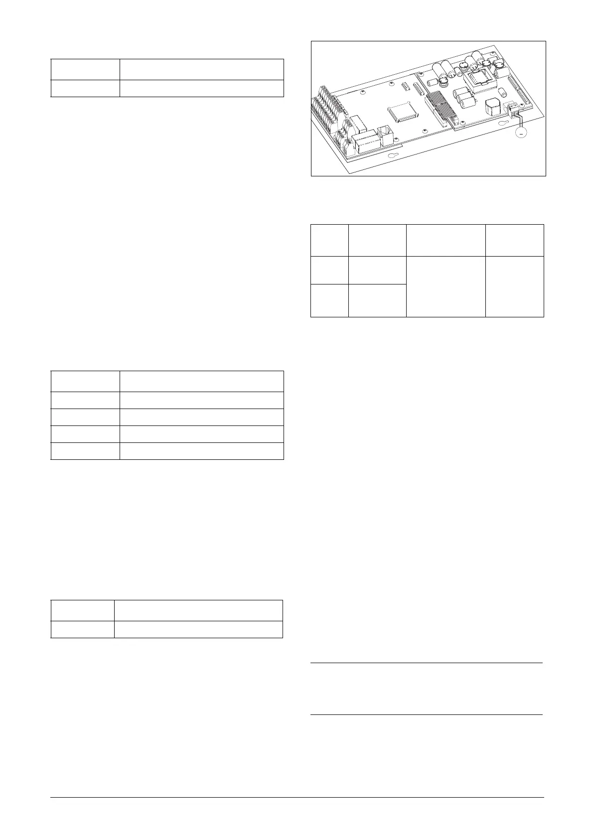
13.7 Standby supply board
option
The standby supply board option provides the possibility of
keeping the communication system up and running without
having the 3-phase mains connected. One advantage is that
the system can be set up without mains power. The option
will also give backup for communication failure if main
power is lost.
The standby supply board option is supplied with external
±10% 24 V
DC
or 24 V
AC,
protected by a 2 A slow acting
fuse, from a double isolated transformer. The terminals X1:1
and X1:2 are voltage polarity independent.
Fig. 111 Connection of standby supply option
13.8 Safe Stop option
To realize a Safe Stop configuration in accordance with
EN-IEC 62061:2005 SIL 2 & EN-ISO 13849-1:2006, the
following three parts need to be attended to:
1. Inhibit trigger signals with safety relay K1 (via Safe Stop
option board).
2. Enable input and control of VSD (via normal I/O con-
trol signals of VSD).
3. Power conductor stage (checking status and feedback of
driver circuits and IGBT’s).
To enable the VSD to operate and run the motor, the fol-
lowing signals should be active:
• "Inhibit" input, terminals 1 (DC+) and 2 (DC-) on the
Safe Stop option board should be made active by con-
necting 24 V
DC
to secure the supply voltage for the
driver circuits of the power conductors via safety relay
K1. See also Fig. 114.
• High signal on the digital input, e.g. terminal 10 in Fig.
114, which is set to "Enable". For setting the digital
input please refer to section 11.5.2, page 119.
These two signals need to be combined and used to enable
the output of the VSD and make it possible to activate a
Safe Stop condition.
Order number Description
01-3876-01 I/O option board 2.0
Order number Description
01-3876-04 RS232/485
01-3876-05 Profibus DP
01-3876-06 DeviceNet
01-3876-09 Modbus/TCP, Ethernet
Order number Description
01-3954-00 Standby power supply kit for after mounting
Ta b l e 3 6
X1
terminal
Name Function Specification
1 Ext. supply 1
External, VSD main
power independ-
ent, supply voltage
for control and com-
munication circuits
24 V
DC
or 24
V
AC
±10%
Double iso-
lated
2 Ext. supply 2
NOTE: The "Safe Stop" condition according to EN-IEC
62061:2005 SIL 2 & EN-ISO 13849-1:2006, can only be
realized by de-activating both the "Inhibit" and "Enable"
inputs.
Must be
double
isolated
X1:1 Left terminal
X1:2 Right terminal
X1

 Loading...


