Emotron AB 01-4429-01r2 Getting Started 27
5. Getting Started
This chapter is a step by step guide that will show you the
quickest way to get the motor shaft turning. We will show
you two examples, remote control and local control.
We assume that the VSD is mounted on a wall or in a cabi-
net as in the chapter 2. page 9.
First there is general information of how to connect mains,
motor and control cables. The next section describes how to
use the function keys on the control panel. The subsequent
examples covering remote control and local control describe
how to program/set the motor data and run the VSD and
motor.
5.1 Connect the mains and
motor cables
Dimension the mains and motor cables according to local
regulations. The cable must be able to carry the VSD load
current.
5.1.1 Mains cables
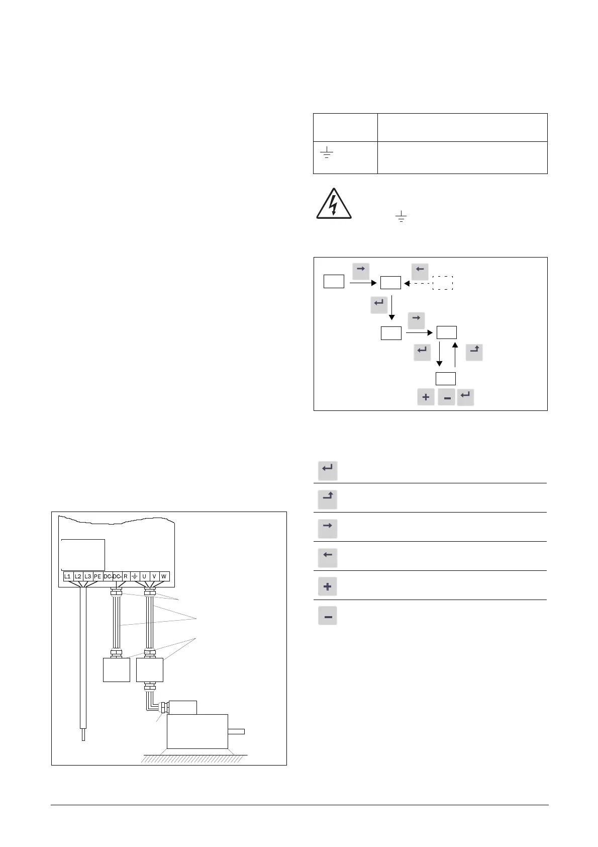
1. Connect the mains cables as in Fig. 34. The VSD has, as
standard, a built-in RFI mains filter that complies with
category C3 which suits the Second Environment stand-
ard.
5.1.2 Motor cables
2. Connect the motor cables as in Fig. 34. To comply with
the EMC Directive you have to use screened cables and
the motor cable screen has to be connected on both
sides: to the housing of the motor and the housing of the
VSD.
Fig. 34 Connection of mains and motor cables
WARNING: In order to work safely the mains
earth must be connected to PE and the motor
earth to .
5.2 Using the function keys
Fig. 35 Example of menu navigation when entering motor
voltage
Metal EMC cable
glands
Screened cables
Metal housing
Table 16 Mains and motor connection
L1,L2,L3
PE
Mains supply, 3 -phase
Safety earth
U, V, W
Motor earth
Motor output, 3-phase
step to lower menu level or confirm changed setting
step to higher menu level or ignore changed setting
step to next menu on the same level
step to previous menu on the same level
increase value or change selection
decrease value or change selection

 Loading...


