Emotron AB 01-4429-01r2 Functional Description 127
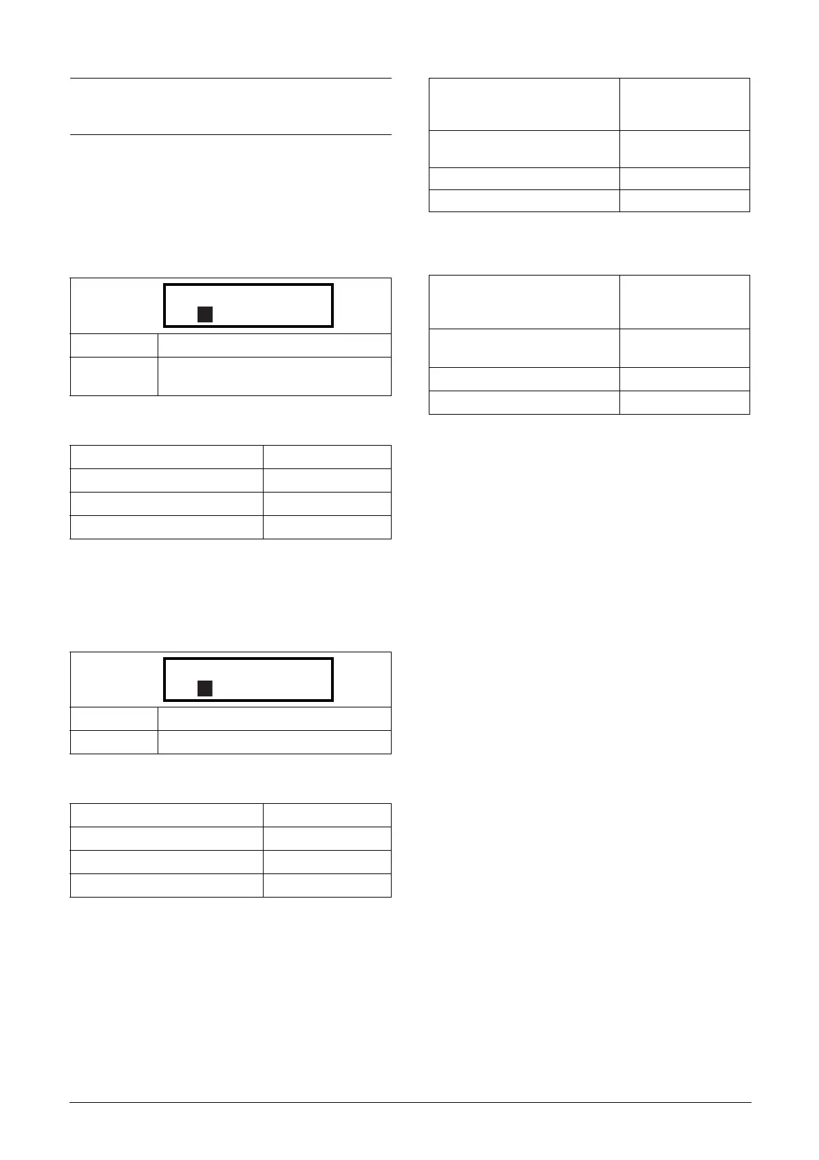
Virtual Connection 1 Destination [561]
With this function the destination of the virtual connection
is established. When a function can be controlled by several
sources, e.g. VC destination or Digital Input, the function
will be controlled in conformity with “OR logic”. See DigIn
for descriptions of the different selections.
Communication information
Virtual Connection 1 Source [562]
With this function the source of the virtual connection is
defined. See DigOut 1 for description of the different selec-
tions.
Communication information
Virtual Connections 2-8 [563] to [56G]
Same function as virtual connection 1 [561] and [562].
Communication information for virtual connections 2-8
Destination.
Communication information for virtual connections 2-8
Source.
11.6 Logical Functions and
Timers [600]
With the Comparators, Logic Functions and Timers, condi-
tional signals can be programmed for control or signalling
features. This gives you the ability to compare different sig-
nals and values in order to generate monitoring/controlling
features.
11.6.1 Comparators [610]
The comparators available make it possible to monitor dif-
ferent internal signals and values, and visualize via digital
output or a contact, when a specific value or status is reached
or established.
There are 2 analogue comparators that compare any availa-
ble analogue value (including the analogue reference inputs)
with two adjustable constants.
For the two analogue comparators two different constants
are available, Level HI and Level LO. With these two levels,
it is possible to create a clear hysteresis for the analogue com-
parator between setting and resetting the comparator out-
put. This function gives a clear difference in switching levels,
which lets the process adapt until a certain action is started.
With such a hysteresis, even an instable analogue signal can
be monitored without getting a nervous comparator signal.
Another function is to get a clear indication that a certain
situation has occurred; the comparator can latch by set Level
LO to a higher value than Level HI.
There are 2 digital comparators that compare any available
digital signal.
The output signals of these comparators can be logically tied
together to yield a logical output signal.
All the output signals can be programmed to the digital or
relay outputs or used as a source for the virtual connections
[560].
NOTE: When a digital input and a virtual destination are
set to the same function, this function will act as an OR
logic function.
Default: Off
Selection:
Same selections as for Digital Input 1,
menu [521].
Modbus Instance no/DeviceNet no: 43281
Profibus slot/index 169/185
Fieldbus format UInt
Modbus format UInt
Default: Off
Selection: Same as for menu [541].
Modbus Instance no/DeviceNet no: 43282
Profibus slot/index 169/186
Fieldbus format UInt
Modbus format UInt
Modbus Instance no/DeviceNet no:
43283, 43285, 43287,
43289, 43291, 43293,
43295
Profibus slot/index
169/ 187, 189, 191,
193, 195, 197, 199
Fieldbus format UInt
Modbus format UInt
Modbus Instance no/DeviceNet no:
43284, 43286, 43288,
43290, 43292, 43294,
43296
Profibus slot/index
169/ 188, 190, 192,
194, 196, 198, 200
Fieldbus format UInt
Modbus format UInt

 Loading...


