22 Control Connections Emotron AB 01-4429-01r2
4.2 Terminal connections
The terminal strip for connecting the control signals is
accessible after opening the front panel.
The table describes the default functions for the signals. The
inputs and outputs are programmable for other functions as
described in chapter 11. page 55. For signal specifications
refer to chapter 14. page 159.
4.3 Inputs configuration
with the switches
The switches S1 to S4 are used to set the input configuration
for the 4 analogue inputs AnIn1, AnIn2, AnIn3 and AnIn4
as described in table 15. See Fig. 28 for the location of the
switches.
NOTE: The maximum total combined current for outputs
11, 20 and 21 is 100mA.
Table 14 Control signals
Terminal Name Function (Default)
Outputs
1 +10 V +10 VDC supply voltage
6 -10 V -10 VDC supply voltage
7 Common Signal ground
11 +24 V +24 VDC supply voltage
12 Common Signal ground
15 Common Signal ground
Digital inputs
8DigIn 1RunL (reverse)
9DigIn 2RunR (forward)
10 DigIn 3 Off
16 DigIn 4 Off
17 DigIn 5 Off
18 DigIn 6 Off
19 DigIn 7 Off
22 DigIn 8 RESET
Digital outputs
20 DigOut 1 Ready
21 DigOut 2 Brake
Analogue inputs
2AnIn 1Process Ref
3AnIn 2Off
4AnIn 3Off
5AnIn 4Off
Analogue outputs
13 Speed Min speed to max speed
14 Torque 0 to max torque
Relay outputs
31 N/C 1
Relay 1 output
Trip, active when the VSD is in a
TRIP condition.
32 COM 1
33 N/O 1
41 N/C 2
Relay 2 output
Run, active when the VSD is
started.
42 COM 2
43 N/O 2
51 COM 3
Relay 3 output
Off
52 N/O 3
NOTE: N/C is opened when the relay is active and N/O is
closed when the relay is active.
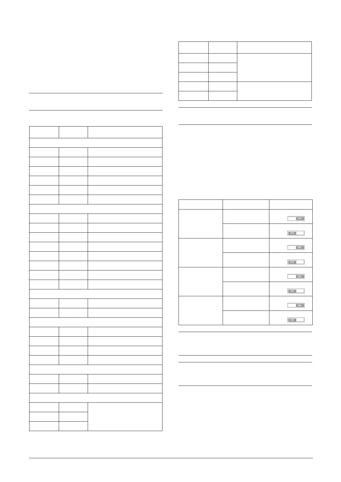
Table 15 Switch settings
Input Signal type Switch
AnIn1
Voltage
S1
Current (default)
S1
AnIn2
Voltage
S2
Current (default)
S2
AnIn3
Voltage
S3
Current (default)
S3
AnIn4
Voltage
S4
Current (default)
S4
NOTE: Scaling and offset of AnIn1 - AnIn4 can be
configured using the software. See menus [512], [515],
[518] and [51B] in section 11.5, page 112.
NOTE: the 2 analogue outputs AnOut 1 and AnOut 2 can
be configured using the software. See menu [530]
section 11.5.3, page 120
Table 14 Control signals
Terminal Name Function (Default)

 Loading...


