Emotron AB 01-4429-01r2 Installation 15
3. Installation
The description of installation in this chapter complies with
the EMC standards and the Machine Directive.
Select cable type and screening according to the EMC
requirements valid for the environment where the VSD is
installed.
3.1 Before installation
Read the following checklist and think through your appli-
cation before installation.
• External or internal control.
• Long motor cables (>100m), refer to section Long motor
cables.
• Motors in parallel, refer to menu [213].
• Functions.
• Suitable VSD size in proportion to the motor/applica-
tion.
• Mount separately supplied option boards according to
the instructions in the appropriate option manual.
If the VSD is temporarily stored before being connected,
please check the technical data for environmental condi-
tions. If the VSD is moved from a cold storage room to the
room where it is to be installed, condensation can form on
it. Allow the VSD to become fully acclimatised and wait
until any visible condensation has evaporated before con-
necting the mains voltage.
3.2 Cable connections for 003
to 073
3.2.1 Mains cables
Dimension the mains and motor cables according to local
regulations. The cable must be able to carry the VSD load
current.
Recommendations for selecting mains
cables
• To fulfil EMC purposes it is not necessary to use
screened mains cables.
• Use heat-resistant cables, +60°C or higher.
• Dimension the cables and fuses in accordance with local
regulations and the nominal current of the motor. See
table 49, page 167.
• The litz ground connection see fig. 23, is only necessary
if the mounting plate is painted. All the variable speed
drives have an unpainted back side and are therefore
suitable for mounting on an unpainted mounting plate.
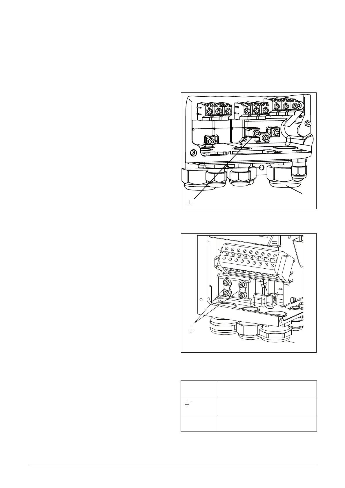
Connect the mains cables according to fig. 20 or 21. The
VSD has as standard a built-in RFI mains filter that com-
plies with category C3 which suits the Second Environment
standard.
Fig. 20 Mains and motor connections, 003-018
Fig. 21 Mains and motor connections, 026-046
Table 6 Mains and motor connection
L1,L2,L3
PE
Mains supply, 3 -phase
Safety earth (protected earth)
U, V, W
Motor earth
Motor output, 3-phase
(DC-),DC+,R
Brake resistor, DC-link
connections (optional)
Screen connection
of motor cables
PE
L
1
L
2
L
3
D
C
-
D
C
+
R
U
V
W
PE
Screen connection
of motor cables

 Loading...


