16 Installation Emotron AB 01-4429-01r2
3.2.2 Motor cables
To comply with the EMC emission standards the variable
speed drive is provided with a RFI mains filter. The motor
cables must also be screened and connected on both sides. In
this way a so-called “Faraday cage” is created around the
VSD, motor cables and motor. The RFI currents are now
fed back to their source (the IGBTs) so the system stays
within the emission levels.
Recommendations for selecting motor
cables
• Use screened cables according to specification in table 7.
Use symmetrical shielded cable; three phase conductors
and a concentric or otherwise symmetrically constructed
PE conductor, and a shield.
• When the conductivity of the cable PE conductor is
<50% of the conductivity of the phase conductor, a sep-
arate PE conductor is required.
• Use heat-resistant cables, +60°C or higher.
• Dimension the cables and fuses in accordance with the
nominal output current of the motor. See table 49, page
167.
• Keep the motor cable between VSD and motor as short
as possible.
• The screening must be connected with a large contact
surface of preferable 360
° and always at both ends, to
the motor housing and the VSD housing. When painted
mounting plates are used, do not be afraid to scrape
away the paint to obtain as large contact surface as possi-
ble at all mounting points for items such as saddles and
the bare cable screening. Relying just on the connection
made by the screw thread is not sufficient.
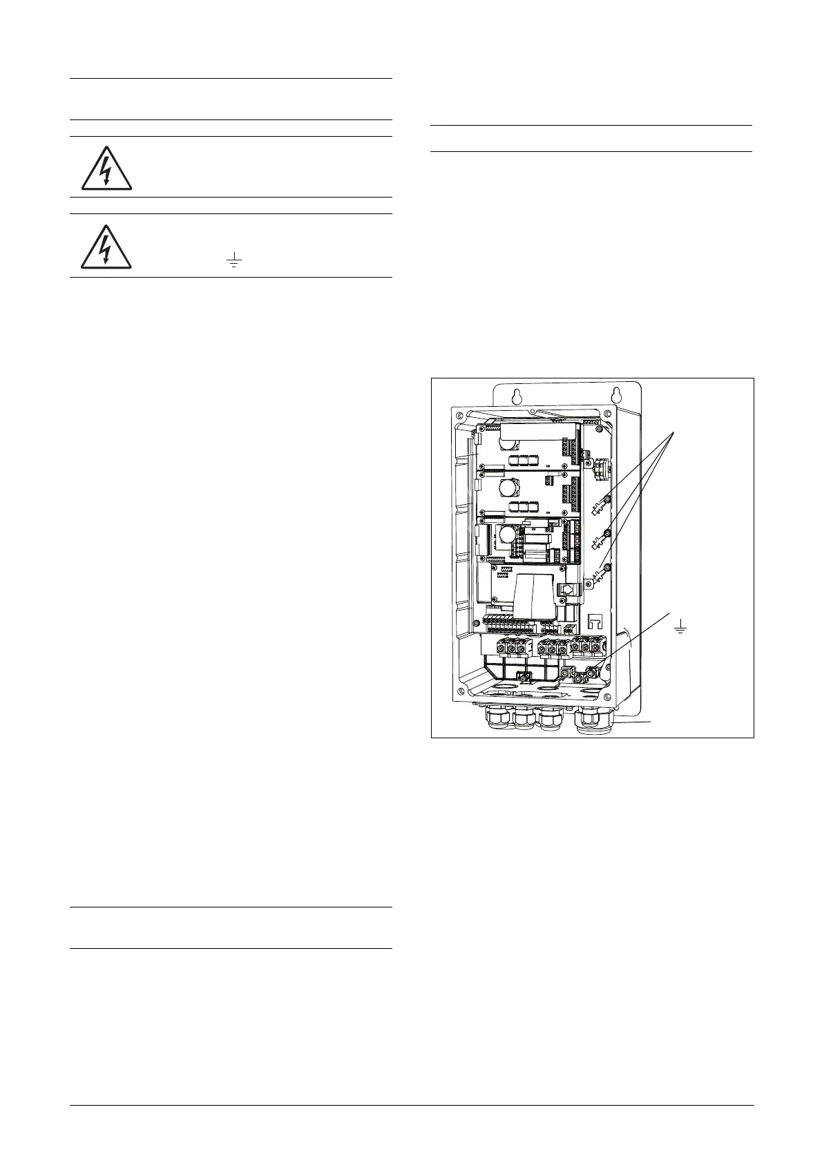
• The litz ground connection, see fig. 24, is only necessary
if the mounting plate is painted. All the variable speed
drives have an unpainted back side and are therefore
suitable for mounting on an unpainted mounting plate.
Connect the motor cables according to U - U, V - V and
W - W, see Fig. 20 and Fig. 21.
Switches between the motor and the
VSD
If the motor cables are to be interrupted by maintenance
switches, output coils, etc., it is necessary that the screening
is continued by using metal housing, metal mounting plates,
etc. as shown in the Fig. 23.
Fig. 24 shows an example when there is no metal mounting
plate used (e.g. if IP54 variable speed drives are used). It is
important to keep the “circuit” closed, by using metal hous-
ing and cable glands.
Fig. 22 Screen connection of cables.
Pay special attention to the following points:
• If paint must be removed, steps must be taken to prevent
subsequent corrosion. Repaint after making connections!
• The fastening of the whole variable speed drive housing
must be electrically connected with the mounting plate
over an area which is as large as possible. For this purpose
the removal of paint is necessary. An alternative method
is to connect the variable speed drive housing to the
mounting plate with as short a length of litz wire as pos-
sible.
• Try to avoid interruptions in the screening wherever pos-
sible.
• If the variable speed drive is mounted in a standard cabi-
net, the internal wiring must comply with the EMC
standard. Fig. 23 shows an example of a VSD built into a
cabinet.
NOTE: The Brake and DC-link Terminals are only fitted if
the Brake Chopper Option is built-in.
WARNING: The Brake Resistor must be
connected between terminals DC+ and R.
WARNING: In order to work safely, the mains
earth must be connected to PE and the
motor earth to .
NOTE: It is important that the motor housing has the
same earth potential as the other parts of the machine.
NOTE: The terminals DC-, DC+ and R are options.
Screen connection
of signal cables
PE
Motor cable
shield connection

 Loading...


