Emotron AB 01-4429-01r2 Operation via the Control Panel 43
9. Operation via the Control Panel
This chapter describes how to use the control panel. The
VSD can be delivered with a control panel or a blank panel.
9.1 General
The control panel displays the status of the VSD and is used
to set all the parameters. It is also possible to control the
motor directly from the control panel. The control panel
can be built-in or located externally via serial communica-
tion. The VSD can be ordered without the control panel.
Instead of the control panel there will be a blank panel.
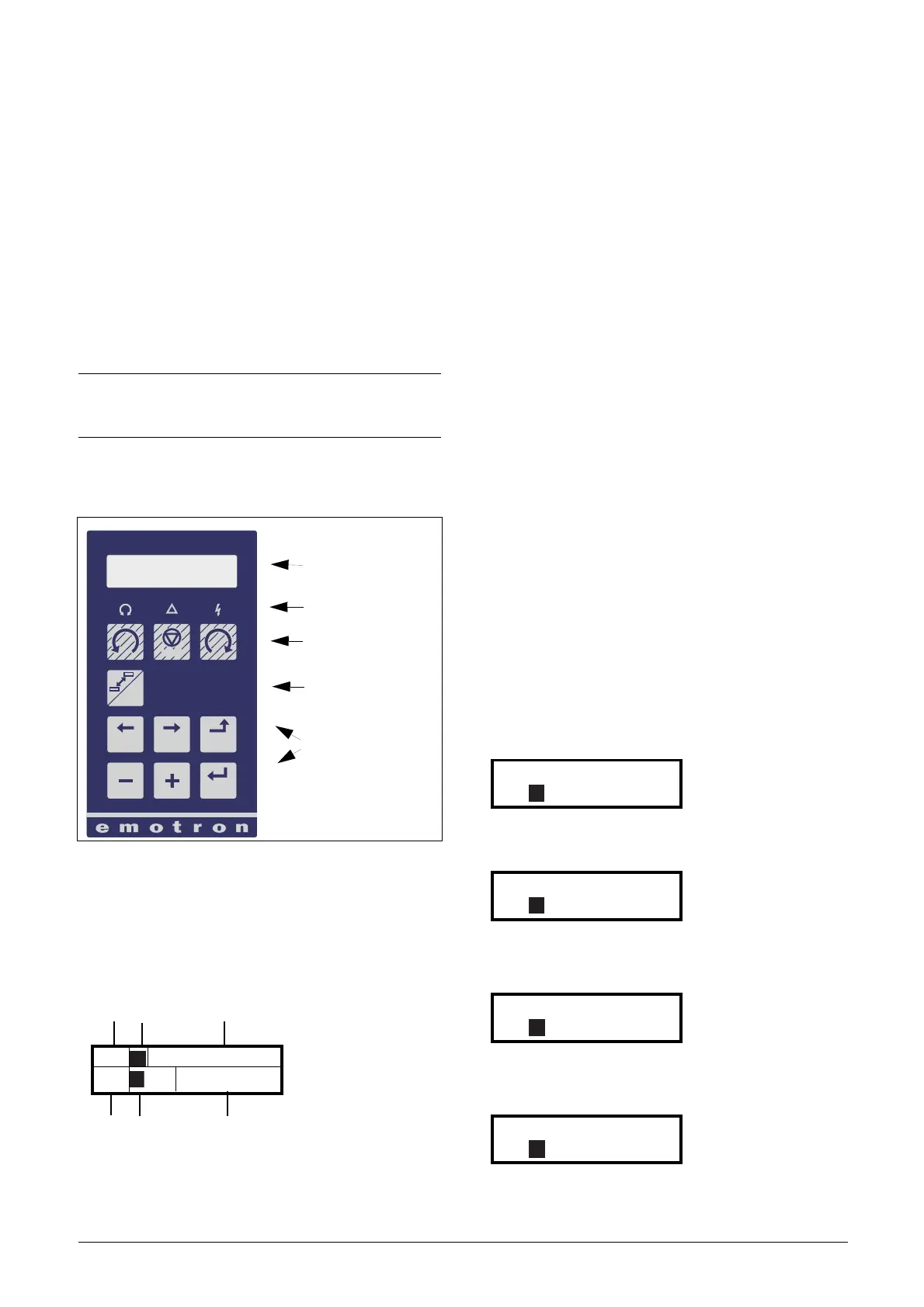
9.2 The control panel
Fig. 45 Control panel
9.2.1 The display
The display is back lit and consists of 2 rows, each with
space for 16 characters. The display is divided into six areas.
The different areas in the display are described below:
Fig. 46 The display
Area A: Shows the actual menu number (3 or 4
digits).
Area B Shows if the menu is in the toggle loop or the
VSD is set for Local operation.
Area C: Shows the heading of the active menu.
Area D: Shows the status of the VSD (3 digits).
The following status indications are possible:
Acc : Acceleration
Dec : Deceleration
I
2
t : Active I
2
t protection
Run : Motor runs
Tr p : Tripped
Stp : Motor is stopped
VL : Operating at Voltage limit
SL : Operating at Speed limit
CL : Operating at Current limit
TL : Operating at Torque limit
OT : Operating at Temperature Limit
LV : Operating at Low Voltage
Sby : Operating from Standby power supply
SST : Operating Safe Stop, is blinking when
activated
LCL : Operating with low cooling liquid level
Area E: Shows active parameter set and if it is a motor
parameter.
Area F: Shows the setting or selection in the active menu.
This area is empty at the 1st level and 2nd level
menu. This area also shows warnings and alarm
messages.
Fig. 47 Example 1st level menu
Fig. 48 Example 2nd level menu
Fig. 49 Example 3d level menu
Fig. 50 Example 4th level menu
NOTE: The VSD can run without the control panel being
connected. However the settings must be such that all
control signals are set for external use.
LC Display
LEDs
Control Keys
Toggle Key
Function Keys
PREV NEXT ESC
ENTER
RESET
LOC/
REM
221 Motor Volt
Stp M1: 400V
221 Motor Volt
Stp M1: 400V

 Loading...


