Emotron AB 01-4429-01r2 Main Features 37
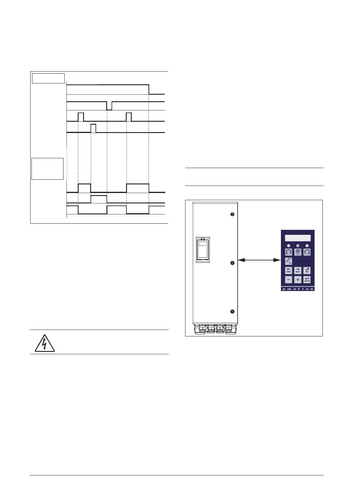
See Fig. 40. The Enable and Stop input must be active con-
tinuously in order to accept any run-right or run-left com-
mand. The last edge (RunR or RunL) is valid. Fig. 42 gives
an example of a possible sequence.
Fig. 42 Input and output status for edge-control
7.3 Performing an
Identification Run
To get the optimum performance out of your VSD/motor
combination, the VSD must measure the electrical parame-
ters (resistance of stator winding, etc.) of the connected
motor. See menu [229], Motor ID-Run.
It is recommended that the extended ID run be used before
the motor is installed in the application.
If this is not possible, the short ID run should be used.
7.4 Using the Control Panel
Memory
Data can be copied from the VSD to the memory in the
control panel and vice versa. To copy all data (including
parameter set A-D and motor data) from the VSD to the
control panel, select Copy to CP[244], Copy to CP.
To copy data from the control panel to the VSD, enter the
menu [245], Load from CP and select what you want to
copy.
The memory in the control panel is useful in applications
with VSDs without a control panel and in applications
where several variable speed drives have the same setup. It
can also be used for temporary storage of settings. Use a con-
trol panel to upload the settings from one VSD and then
move the control panel to another VSD and download the
settings.
Fig. 43 Copy and load parameters between VSD and control
panel
WARNING: During the extended ID RUN, the
motor shaft will rotate. Take safety measures to
avoid unforeseen dangerous situations.
INPUTS
ENABLE
STOP
RUN R
RUN L
OUTPUT
STATUS
Right rotation
Left rotation
Standstill
NOTE: Load from and copy to the VSD is only possible
when the VSD is in stop mode.

 Loading...


