36 Main Features Emotron AB 01-4429-01r2
Fig. 39 Functionality of the Stop and Enable input
Reset and Autoreset operation
If the VSD is in Stop Mode due to a trip condition, the
VSD can be remotely reset by a pulse (“low” to “high” tran-
sition) on the Reset input, default on DigIn 8. Depending
on the selected control method, a restart takes place as fol-
lows:
Level-control
If the Run inputs remain in their position the VSD will start
immediately after the Reset command is given.
Edge-control
After the Reset command is given a new Run command
must be applied to start the VSD again.
Autoreset is enabled if the Reset input is continuously active.
The Autoreset functions are programmed in menu Autoreset
[250].
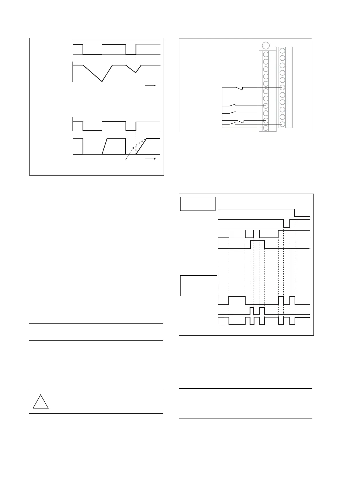
Run Inputs Level-controlled.
The inputs are set as default for level-control. This means
that an input is activated by making the input continuously
“High”. This method is commonly used if, for example,
PLCs are used to operate the VSD.
The examples given in this and the following paragraphs fol-
low the input selection shown in Fig. 40.
Fig. 40 Example of wiring for Run/Stop/Enable/Reset inputs
The Enable input must be continuously active in order to
accept any run-right or run-left command. If both RunR
and RunL inputs are active, then the VSD stops according
to the selected Stop Mode. Fig. 41 gives an example of a pos-
sible sequence.
Fig. 41 Input and output status for level-control
Run Inputs Edge-controlled
Menu [21A] Start signal Level/Edge must be set to Edge to
activate edge control. This means that an input is activated
by a “low” to “high” transition or vice versa.
NOTE: If the control commands are programmed for
Keyboard control or Com, Autoreset is not possible.
CAUTION: Level-controlled inputs DO NOT
comply with the Machine Directive, if the inputs
are directly used to start and stop the machine.
(06-F104_NG)
t
t
STOP
(STOP=DECEL)
OUTPUT
SPEED
ENABLE
OUTPUT
SPEED
(or if Spinstart is selected)
NOTE: Edge-controlled inputs comply with the Machine
Directive (see chapter EMC and Machine Directive), if
the inputs are directly used for starting and stopping the
machine.
X1
1
12
22
11
2
3
4
5
6
7
8
9
10
13
14
15
16
17
18
19
20
21
Stop
Reset
+24 V
RunL
RunR
Enable
INPUTS
OUTPUT
STATUS
ENABLE
STOP
RUN R
RUN L
Right rotation
Left rotation
Standstill

 Loading...


