10 Mounting Emotron AB 01-4429-01r2
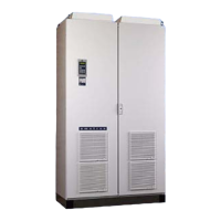
Fig. 5 Lifting VSD model -300 to -1500
2.2 Stand-alone units
The VSD must be mounted in a vertical position against a
flat surface. Use the template (delivered together with the
VSD) to mark out the position of the fixing holes.
Fig. 6 Variable speed drive mounting models 003 to 1500
2.2.1 Cooling
Fig. 6 shows the minimum free space required around the
VSD for the models 003 to 1500 in order to guarantee ade-
quate cooling. Because the fans blow the air from the bot-
tom to the top it is advisable not to position an air inlet
immediately above an air outlet.
The following minimum separation between two variable
speed drives, or a VSD and a non-dissipating wall must be
maintained. Valid if free space on opposite side.
Table 4 Mounting and cooling
003-018 026-046 090-250
300-1500
cabinet
VFX-VFX,
side-by-side
(mm)
a 200 200 200 100
b 200 200 200 0
c0 0 0 0
d0 0 0 0
VFX-wall,
wall-one
side
(mm)
a 100 100 100 100
b 100 100 100 0
c0 0 0 0
d0 0 0 0
NOTE: When a 300 to 1500 model is placed between two
walls, a minimum distance at each side of 200 mm must
be maintained.

 Loading...