28 Getting Started Emotron AB 01-4429-01r2
5.3 Remote control
In this example external signals are used to control the VSD/
motor.
A standard 4-pole motor for 400 V, an external start button
and a reference value will also be used.
5.3.1 Connect control cables
Here you will make up the minimum wiring for starting. In
this example the motor/VSD will run with right rotation.
To comply with the EMC standard, use screened control
cables with plaited flexible wire up to 1.5 mm
2
or solid wire
up to 2.5 mm
2
.
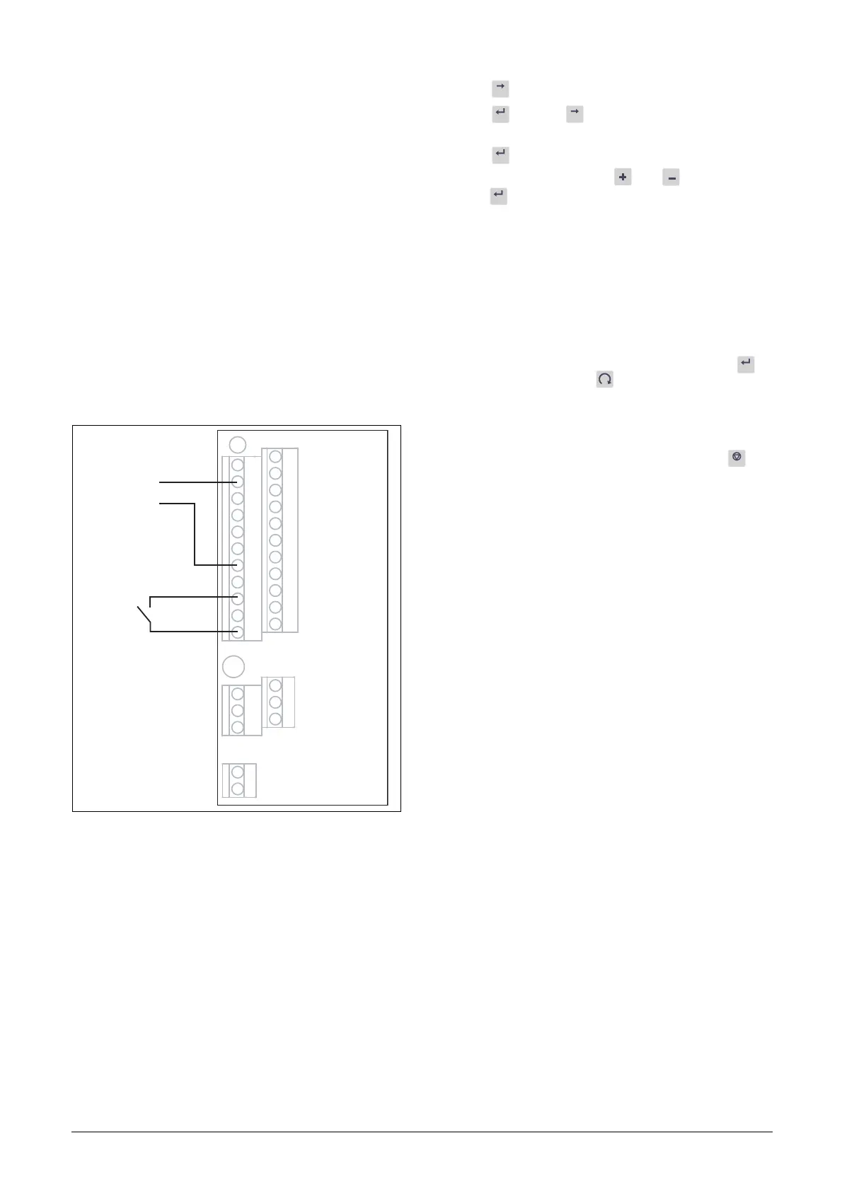
3. Connect a reference value between terminals 7 (Com-
mon) and 2 (AnIn 1) as in Fig. 36.
4. Connect an external start button between terminal 11
(+24 VDC) and 9 (DigIn2, RUNR) as in Fig. 36.
Fig. 36 Wiring
5.3.2 Switch on the mains
Close the door to the VSD. Once the mains is switched on,
the internal fan in the VSD will run for 5 seconds.
5.3.3 Set the Motor Data
Enter correct motor data for the connected motor. The
motor data is used in the calculation of complete operational
data in the VSD.
Change settings using the keys on the control panel. For fur-
ther information about the control panel and menu struc-
ture, see the chapter 9. page 43.
Menu [100], Preferred View is displayed when started.
1. Press to display menu [200], Main Setup.
2. Press and then to display menu [220], Motor
Data.
3. Press to display menu [221] and set motor voltage.
4. Change the value using the and keys. Confirm
with .
5. Set motor frequency [222].
6. Set motor power [223].
7. Set motor current [224].
8. Set motor speed [225].
9. Set power factor (cos ϕ) [227].
10. Select supply voltage level used [21B]
11. [229] Motor ID run: Choose Short, confirm with
and give start command .
The VSD will now measure some motor parameters.
The motor makes some beeping sounds but the shaft
does not rotate. When the ID run is finished after about
one minute ("Test Run OK!" is displayed), press to
continue.
12. Use AnIn1 as input for the reference value. The default
range is 4-20 mA. If you need a 0-10 V reference value,
change switch (S1) on control board and set [512] Anln
1 Set-up to 0-10V.
13. Switch off power supply.
14. Connect digital and analogue inputs/outputs as in
Fig. 36.
15. Ready!
16. Switch on power supply.
5.3.4 Run the VSD
Now the installation is finished, and you can press the exter-
nal start button to start the motor.
When the motor is running the main connections are OK.
X2
X3
X1
1
12
22
11
41
42
43
31
32
33
51
52
2
3
4
5
6
7
8
9
10
13
14
15
16
17
18
19
20
21

 Loading...


