124 Functional Description Emotron AB 01-4429-01r2
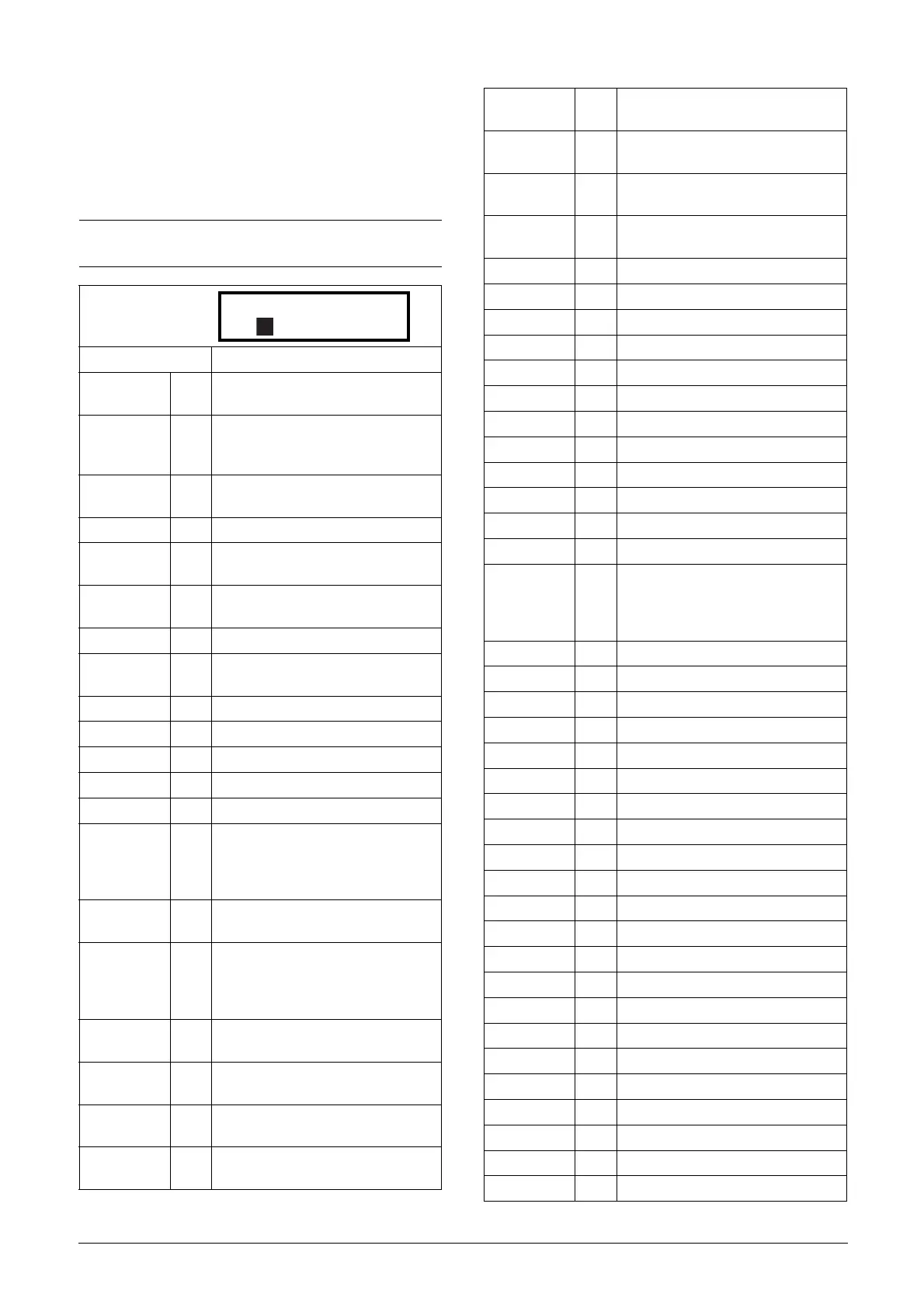
11.5.4 Digital Outputs [540]
Submenu with all the settings for the digital outputs.
Digital Out 1 [541]
Sets the function for the digital output 1.
NOTE: The definitions described here are valid for the
active output condition.
Default: Ready
Off 0
Output is not active and constantly
low.
On 1
Output is made constantly high, i.e.
for checking circuits and trouble
shooting.
Run 2
Running. The VSD output is active =
produces current for the motor.
Stop 3 The VSD output is not active.
0Hz 4
The output frequency=0±0.1Hz when
in Run condition.
Acc/Dec 5
The speed is increasing or decreasing
along the acc. ramp dec. ramp.
At Process 6 The output = Reference.
At Max spd 7
The frequency is limited by the Maxi-
mum Speed.
No Trip 8 No Trip condition active.
Trip 9 A Trip condition is active.
AutoRst Trip 10 Autoreset trip condition active.
Limit 11 A Limit condition is active.
Warning 12 A Warning condition is active.
Ready 13
The VSD is ready for operation and to
accept a start command. This means
that the VSD is powered up and
healthy.
T= T
lim
14
The torque is limited by the torque
limit function.
I>I
nom
15
The output current is higher than the
motor nominal current [224], reduced
according to Motor ventilation [228],
see Fig. 59.
Brake 16
The output is used to control a
mechanical brake.
Sgnl<Offset 17
One of the AnIn input signals is lower
than 75% of the threshold level.
Alarm 18
The max or min alarm level has been
reached.
Pre-Alarm 19
The max or min pre alarm level has
been reached.
Max Alarm 20
The max alarm level has been
reached.
Max PreAlarm 21
The max pre alarm level has been
reached.
Min Alarm 22
The min alarm level has been
reached.
Min PreAlarm 23
The min pre alarm Level has been
reached.
LY 24 Logic output Y.
!LY 25 Logic output Y inverted.
LZ 26 Logic output Z.
!LZ 27 Logic output Z inverted.
CA 1 28 Analogue comparator 1 output.
!A1 29 Analogue comp 1 inverted output.
CA 2 30 Analogue comparator 2 output.
!A2 31 Analogue comp 2 inverted output.
CD 1 32 Digital comparator 1 output.
!D1 33 Digital comp 1 inverted output.
CD 2 34 Digital comparator 2 output.
!D2 35 Digital comp 2 inverted output.
Operation 36
Run command is active or VSD run-
ning. The signal can be used to con-
trol the mains contactor if the VSD is
equipped with Standby supply option.
T1Q 37 Timer1 output
!T1Q 38 Timer1 inverted output
T2Q 39 Timer2 output
!T2Q 40 Timer2 inverted output
Sleeping 41 Sleeping function activated
Crane Deviat 42 Tripped on deviation
Loc/Rem 57 Local/Rem function is active
Standby 58 Standby supply option is active
PTC Trip 59 Trip when function is active
PT100 Trip 60 Trip when function is active
Overvolt 61 Overvoltage due to high main voltage
Overvolt G 62 Overvoltage due to generation mode
Overvolt D 63 Overvoltage due to deceleration
Acc 64 Acceleration along the acc. ramp
Dec 65 Deceleration along the dec. ramp
I
2
t66I
2
t limit protection active
V-Limit 67 Overvoltage limit function active
C-Limit 68 Overcurrent limit function active
Overtemp 69 Over temperature warning
Low voltage 70 Low voltage warning
DigIn 1 71 Digital input 1
DigIn 2 72 Digital input 2

 Loading...


