Emotron AB 01-4429-01r2 Functional Description 67
Communication information
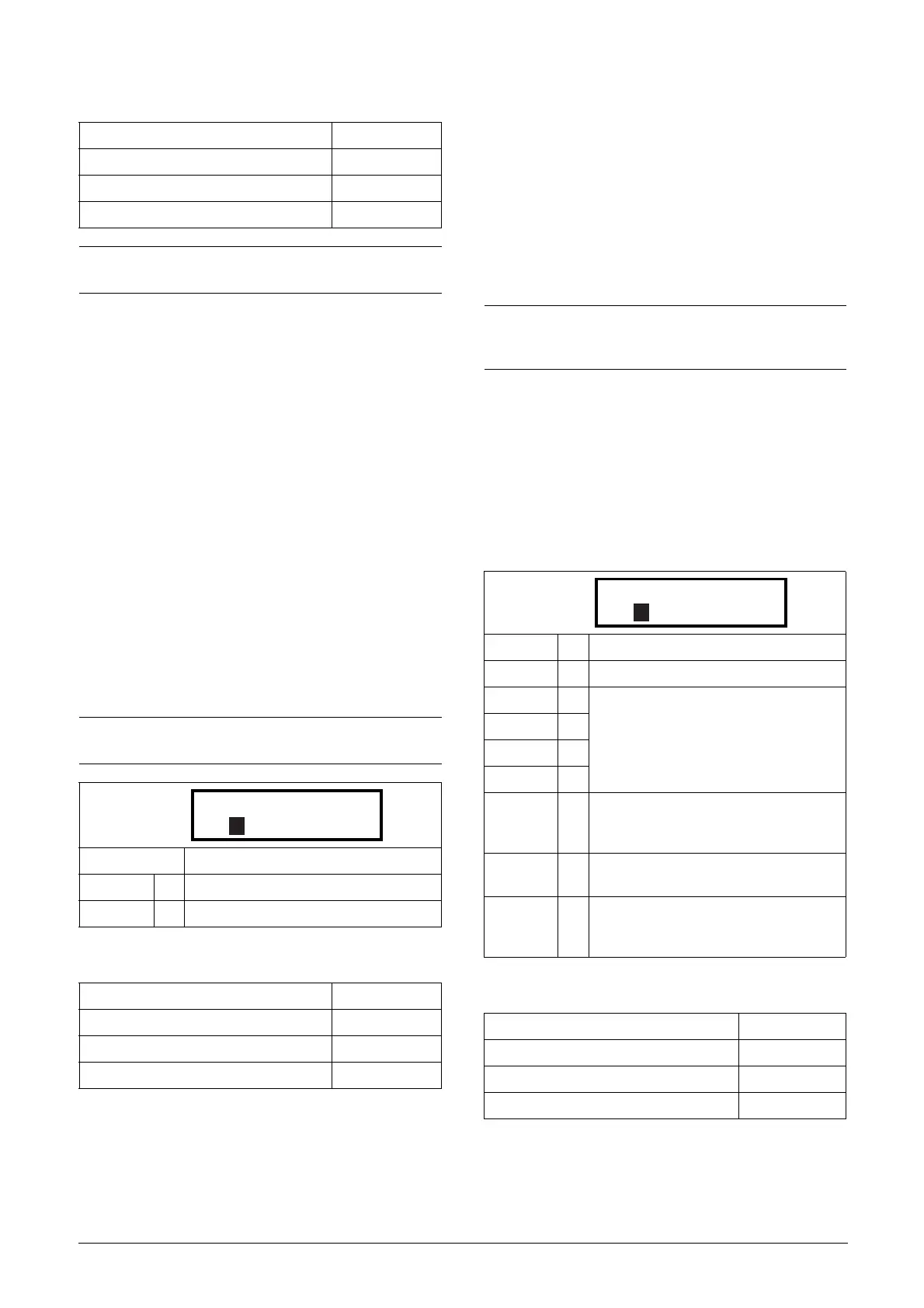
Motor PTC [237]
In this menu the internal motor PTC hardware option is
enabled. This PTC input complies with DIN 44081/44082.
Please refer to the manual for the PTC/PT100 option board
for electrical specification.
This menu is only visible if a PTC (or resistor <2 kOhm) is
connected to terminals X1: 78–79.
To enable the function:
1. Connect the thermistor wires to X1: 78–79 or for testing
the input, connect a resistor to the terminals. Use resistor
value between 50 and 2000 ohm.
Menu [237] will now appear.
2. Enable input by setting menu [237] Motor PTC=On.
If enabled and <50 ohm a sensor error trip will occur. The
message “Motor PTC” is shown.
If the function is disabled and the PTC or resistor is
removed, the menu will disappear after the next power up
Communication information
11.2.6 Parameter Set Handling [240]
There are four different parameter sets available in the VSD.
These parameter sets can be used to set the VSD up for dif-
ferent processes or applications such as different motors used
and connected, activated PID controller, different ramp
time settings, etc.
A parameter set consists of all parameters with the exception
of the menu [211] Language, [217] Local Remote, [218]
Lock Code, [220] Motor Data, [241] Select Set and [260]
Serial Communication.
Select Set [241]
Here you select the parameter set. Every menu included in
the parameter sets is designated A, B, C or D depending on
the active parameter set. Parameter sets can be selected from
the keyboard, via the programmable digital inputs or via
serial communication. Parameter sets can be changed during
the run. If the sets are using different motors (M1 to M4)
the set will be changed when the motor is stopped.
Communication information
Modbus Instance no/DeviceNet no: 43066
Profibus slot/index 168/225
Fieldbus format UInt
Modbus format UInt
NOTE: This menu is only valid for PT 100 thermal
protection.
NOTE: This option is available only for (size B and C)
VFX48/52-003-046.
Default: Off
Off 0 Motor PTC protection is disabled
On 1 Motor PTC protection is enabled
Modbus Instance no/DeviceNet no: 43067
Profibus slot/index 168/226
Fieldbus format UInt
Modbus format UInt
NOTE: Actual timers are common for all sets. When a set
is changed the timer functionality will change according
to the new set, but the timer value will stay unchanged.
Default: A
Selection: A, B, C, D, DigIn, Com, Option
A0
Fixed selection of one of the 4 parameter
sets A, B, C or D.
B1
C2
D3
DigIn 4
Parameter set is selected via a digital
input. Define which digital input in menu
[520], Digital inputs.
Com 5
Parameter set is selected via serial com-
munication.
Option 6
The parameter set is set via an option.
Only available if the option can control the
selection.
Modbus Instance no/DeviceNet no: 43022
Profibus slot/index 168/181
Fieldbus format UInt
Modbus format UInt

 Loading...


