110 Functional Description Emotron AB 01-4429-01r2
The default set levels for the (pre)alarms are:
These default set levels can be manually changed in menus
[416] to [419]. After execution the message “Autoset OK!” is
displayed for 1s and the selection reverts to “No”.
Normal Load [41B]
Set the level of the normal load. The alarm or pre alarm will
be activated when the load is above/under normal load ±
margin.
Communication information
Load Curve [41C]
The load curve function can be used with any smooth load
curve. The curve can be populated with a test-run or the val-
ues can be entered or changed manually.
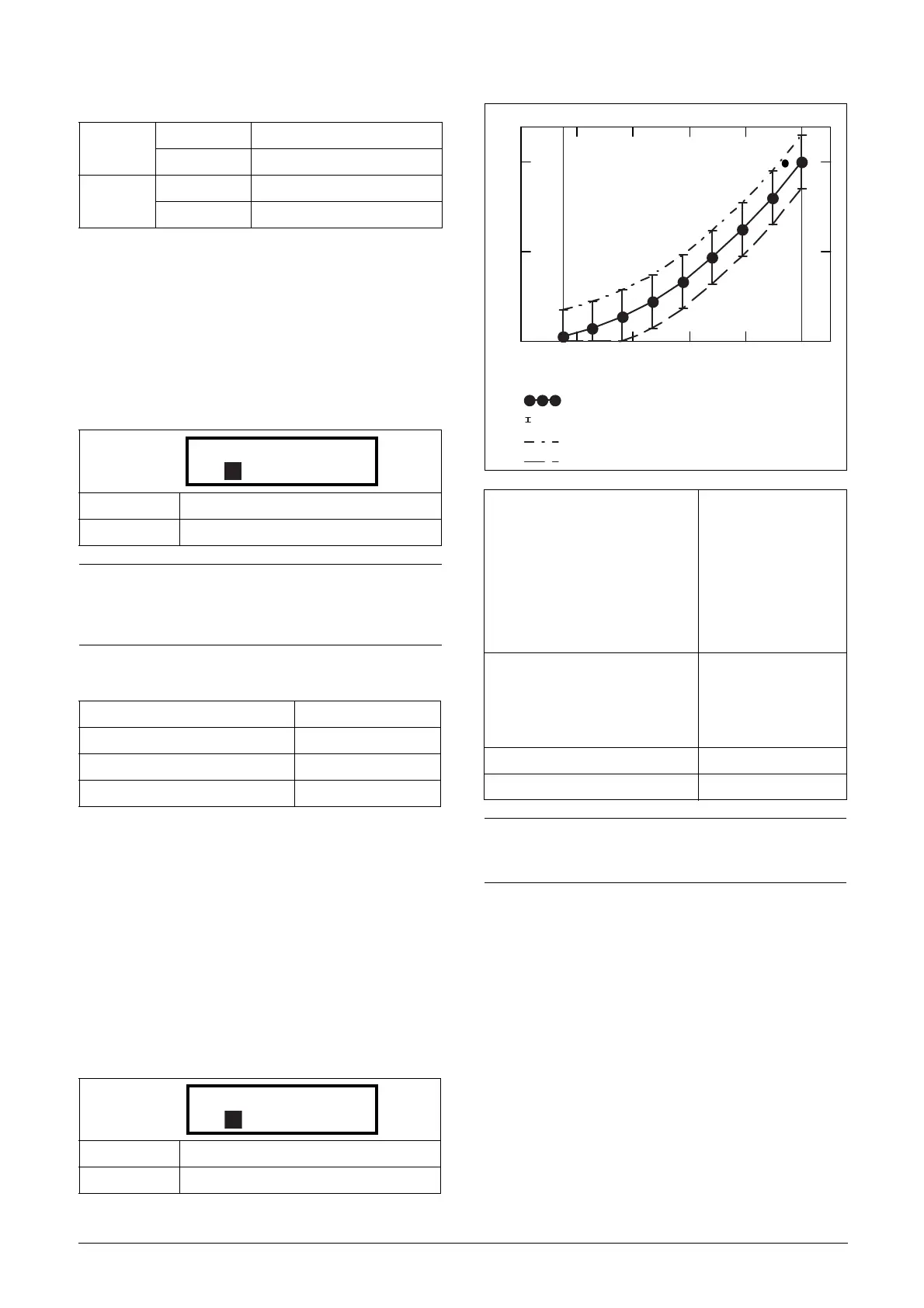
Load Curve 1-9 [41C1]-[41C9]
The measured load curve is based on 9 stored samples. The
curve starts at minimum speed and ends at maximum speed,
the range in between is divided into 8 equal steps. The meas-
ured values of each sample are displayed in [41C1] to
[41C9] and can be adapted manually. The value of the 1st
sampled value on the load curve is displayed.
Communication information
Fig. 87
11.4.2 Process Protection [420]
Submenu with settings regarding protection functions for
the VSD and the motor.
Low Voltage Override [421]
If a dip in the mains supply occurs and the low voltage over-
ride function is enabled, the VSD will automatically
decrease the motor speed to keep control of the application
and prevent an under voltage trip until the input voltage
rises again. Therefore the rotating energy in the motor/load
is used to keep the DC link voltage level at the override level,
for as long as possible or until the motor comes to a stand-
still. This is dependent on the inertia of the motor/load
Overload
Max Alarm menu [4161] + [41B]
Max Pre Alarm menu [4171] + [41B]
Underload
Min Pre Alarm menu [41B] - [4181]
Min Alarm menu [41B] - [4191]
Default: 100%
Range: 0-400% of max torque
NOTE: 100% Torque means: I
NOM
= I
MOT
. The maximum
depends on the motor current and VSD max current
settings, but the absolute maximum adjustment is
400%.
Modbus Instance no/DeviceNet no: 43335
Profibus slot/index 169/239
Fieldbus format Long, 1=1%
Modbus format EInt
Default: 100%
Range: 0–400% of max torque
41C1 Load Curve1
Stp 0rpm 100%
Modbus Instance no/DeviceNet no:
43336%, 43337 rpm,
43338%, 43339 rpm,
43340%, 43341 rpm,
43342%, 43343 rpm,
43344%, 43345 rpm,
43346%, 43347 rpm,
43348%, 43349 rpm,
43350%, 43351 rpm,
43352%, 43353 rpm
Profibus slot/index
169/240, 169/242,
169/244, 169/246,
169/248, 169/250,
169/252, 169/254,
170/1
Fieldbus format Long
Modbus format EInt
NOTE: The speed values depend on the Min- and Max
Speed values. they are read only and cannot be
changed.
0 0.2 0.4 0.6 0.8 1
0
0.5
1
Min Speed
Speed
Max Speed
Min-Max alarm tolerance band graph
Measured load samples
Min-max tolerance band
Max alarm limit
Min alarm limit

 Loading...


