CG Drives & Automation 01-7492-01r1 167
Example
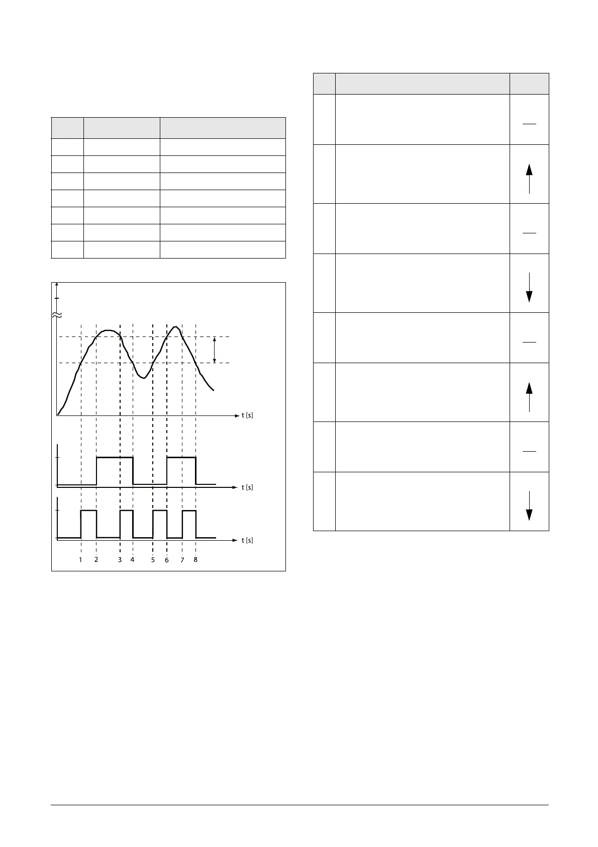
This example describes, both for hysteresis and window type
comparator, the normal use of the constant level high and
low.
Fig. 133
Menu Function Setting
343 Max Speed 1500
561 VC1 Dest Timer 1
562 VC1 Source CA1
6111 CA1 Value Speed
6112 CA1 Level HI 300 rpm
6113 CA1 Level LO 200 rpm
6114 CA1 Type Hysteresis
MAX
speed
[343]
300
200
CA1 Level HI [6112]
CA1 Level LO [6113]
Output
CA1
High
Low
Output
CA1
High
Low
[6114] Hysteresis
[6114] Window
t
t
Hysteresis/Window
band
Table 39 Comments to fig. 133 regarding Hysteresis selection.
No. Description
Hysteresis
1
The reference signal passes the Level LO
value from below (positive edge), the
comparator CA1 does not change, output
stays low.
2
The reference signal passes the Level HI
value from below (positive edge), the
comparator CA1 output is set high.
3
The reference signal passes the Level HI
value from above (negative edge), the
comparator CA1 does not change, output
stays high.
4
The reference signal passes the Level LO
value from above (negative edge), the
comparator CA1 is reset, output is set low.
5
The reference signal passes the Level LO
value from below (positive edge), the
comparator CA1 does not change, output
stays low.
6
The reference signal passes the Level HI
value from below (positive edge), the
comparator CA1 output is set high.
7
The reference signal passes the Level HI
value from above (negative edge), the
comparator CA1 does not change, output
stays high.
8
The reference signal passes the Level LO
value from above (negative edge), the
comparator CA1 is reset, output is set low.

 Loading...

