Cubemass DCI MODBUS RS485 Table of contents
Endress+Hauser 3
Table of contents
1 Safety instructions . . . . . . . . . . . . . . . . 5
1.1 Designated use . . . . . . . . . . . . . . . . . . . . . . . . . . . . 5
1.2 Installation, commissioning and operation . . . . . . . . 5
1.3 Operational safety . . . . . . . . . . . . . . . . . . . . . . . . . . 5
1.4 Return . . . . . . . . . . . . . . . . . . . . . . . . . . . . . . . . . . . 6
1.5 Notes on safety conventions and icons . . . . . . . . . . . 6
1.6 Symbols on nameplates . . . . . . . . . . . . . . . . . . . . . . 6
2 Identification . . . . . . . . . . . . . . . . . . . . 7
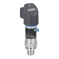
2.1 Device designation . . . . . . . . . . . . . . . . . . . . . . . . . 7
2.1.1 Nameplate of the transmitter . . . . . . . . . . . . 7
2.1.2 Nameplate of the sensor . . . . . . . . . . . . . . . 8
2.1.3 Nameplate for connections . . . . . . . . . . . . . 9
2.1.4 Additional sign – position of the rupture disk 10
2.2 Certificates and approvals . . . . . . . . . . . . . . . . . . . 10
2.3 Registered trademarks . . . . . . . . . . . . . . . . . . . . . . 10
3 Installation . . . . . . . . . . . . . . . . . . . . . 11
3.1 Incoming acceptance, transport and storage . . . . . . 11
3.1.1 Incoming acceptance . . . . . . . . . . . . . . . . . 11
3.1.2 Transport . . . . . . . . . . . . . . . . . . . . . . . . . 11
3.1.3 Storage . . . . . . . . . . . . . . . . . . . . . . . . . . . 11
3.2 Installation conditions . . . . . . . . . . . . . . . . . . . . . . 11
3.2.1 Dimensions . . . . . . . . . . . . . . . . . . . . . . . . 11
3.2.2 Mounting location . . . . . . . . . . . . . . . . . . . 12
3.2.3 Orientation . . . . . . . . . . . . . . . . . . . . . . . . 13
3.2.4 Heating . . . . . . . . . . . . . . . . . . . . . . . . . . . 14
3.2.5 Inlet and outlet runs . . . . . . . . . . . . . . . . . 14
3.2.6 Vibrations . . . . . . . . . . . . . . . . . . . . . . . . . 14
3.2.7 Limiting flow . . . . . . . . . . . . . . . . . . . . . . . 14
3.3 Installation instructions . . . . . . . . . . . . . . . . . . . . . 15
3.3.1 Turning the transmitter housing . . . . . . . . 15
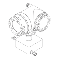
3.3.2 Installing the wall-mount housing . . . . . . . 16
3.3.3 Turning the local display . . . . . . . . . . . . . . 18
3.4 Post-installation check . . . . . . . . . . . . . . . . . . . . . . 18
4 Wiring . . . . . . . . . . . . . . . . . . . . . . . . 19
4.1 MODBUS RS485 cable specifications . . . . . . . . . . . 19
4.1.1 Shielding and grounding . . . . . . . . . . . . . . 20
4.2 Connecting the remote version . . . . . . . . . . . . . . . 21
4.2.1 Connecting the connecting cable for
sensor/transmitter . . . . . . . . . . . . . . . . . . . 21
4.2.2 Cable specification, connecting cable . . . . . 21
4.3 Connecting the measuring unit . . . . . . . . . . . . . . . 22
4.3.1 Transmitter connection . . . . . . . . . . . . . . . 22
4.3.2 Terminal assignment . . . . . . . . . . . . . . . . . 24
4.4 Degree of protection . . . . . . . . . . . . . . . . . . . . . . . 24
4.5 Post-connection check . . . . . . . . . . . . . . . . . . . . . . 25
5 Operation . . . . . . . . . . . . . . . . . . . . . . 26
5.1 Display and operating elements . . . . . . . . . . . . . . . 26
5.1.1 Readings displayed (operation mode) . . . . . 27
5.1.2 Additional display functions . . . . . . . . . . . . 27
5.1.3 Icons . . . . . . . . . . . . . . . . . . . . . . . . . . . . . 28
5.2 Brief guide to the function matrix . . . . . . . . . . . . . . 29
5.2.1 General notes . . . . . . . . . . . . . . . . . . . . . . 30
5.2.2 Enabling the programming mode . . . . . . . . 30
5.2.3 Disabling the programming mode . . . . . . . . 30
5.3 Error messages . . . . . . . . . . . . . . . . . . . . . . . . . . . . 31
5.3.1 Type of error . . . . . . . . . . . . . . . . . . . . . . . 31
5.3.2 Error message type . . . . . . . . . . . . . . . . . . . 31
5.3.3 Confirming error messages . . . . . . . . . . . . . 32
5.4 MODBUS RS485 communication . . . . . . . . . . . . . 32
5.4.1 MODBUS RS485 technology . . . . . . . . . . . 32
5.4.2 MODBUS telegram . . . . . . . . . . . . . . . . . . 34
5.4.3 MODBUS function codes . . . . . . . . . . . . . 35
5.4.4 Maximum number of writes . . . . . . . . . . . 35
5.4.5 MODBUS register addresses . . . . . . . . . . . . 36
5.4.6 MODBUS error messages . . . . . . . . . . . . . . 38
5.4.7 MODBUS auto-scan buffer . . . . . . . . . . . . . 39
5.5 Operating options . . . . . . . . . . . . . . . . . . . . . . . . . 43
5.5.1 Operating program "FieldCare" . . . . . . . . . . 43
5.5.2 Device description files for
operating programs . . . . . . . . . . . . . . . . . . 43
5.6 Switching hardware write protection on/off . . . . . . 44
6 Commissioning . . . . . . . . . . . . . . . . . . 45
6.1 Function check . . . . . . . . . . . . . . . . . . . . . . . . . . . 45
6.2 Switching on the measuring device . . . . . . . . . . . . 45
6.3 Quick Setup . . . . . . . . . . . . . . . . . . . . . . . . . . . . . . 46
6.3.1 Quick Setup "Commissioning" . . . . . . . . . . 46
6.3.2 Quick Setup "Pulsating Flow" . . . . . . . . . . . 48
6.3.3 Quick Setup "Gas measurement" . . . . . . . . 51
6.3.4 Quick Setup "Communication" . . . . . . . . . . 52
6.3.5 Data back-up/transfer . . . . . . . . . . . . . . . . 54
6.4 Configuration . . . . . . . . . . . . . . . . . . . . . . . . . . . . 55
6.4.1 Configuring the device address . . . . . . . . . . 55
6.4.2 Configuring the terminating resistors . . . . . 56
6.4.3 Current output: active/passive . . . . . . . . . . 57
6.4.4 Pulse/frequency output . . . . . . . . . . . . . . . 58
6.4.5 Relay contacts:
Normally closed/Normally open . . . . . . . . 59
6.5 Adjustment . . . . . . . . . . . . . . . . . . . . . . . . . . . . . . 60
6.5.1 Zero point adjustment . . . . . . . . . . . . . . . . 60
6.5.2 Density adjustment . . . . . . . . . . . . . . . . . . 61
6.6 Rupture element . . . . . . . . . . . . . . . . . . . . . . . . . . 63
6.7 Purge and pressure monitoring connections . . . . . . 63
6.8 Memory (HistoROM) . . . . . . . . . . . . . . . . . . . . . . . 64
6.8.1 HistoROM/S-DAT (sensor-DAT) . . . . . . . . 64
6.8.2 HistoROM/T-DAT (transmitter-DAT) . . . . 64
 Loading...