Troubleshooting Cubemass DCI MODBUS RS485
78 Endress+Hauser
A0006811
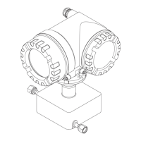
Fig. 39: Field housing: removing and installing printed circuit boards
1 Local display
1.1 Latch
1.2 Ribbon cable (display module)
2 Screws of electronics compartment cover
3 Aperture for installing/removing boards
4 Power unit board
5 Amplifier board
5.1 Signal cable (sensor)
5.2 Excitation current cable (sensor)
5.3 S-DAT (sensor data memory)
5.4 T-DAT (transmitter data memory)
6 I/O board (flexible assignment)
6.1 Optional: pluggable submodules (current output, pulse/frequency output and relay output)
4
5
6
3
3
3
2
1
1.2
5.1
5.3
5.4
5.2
1.1
IN
PU
T/O
U
TPU
T
4
IN
P
UT/O
U
TP
U
T
3
1
2
3
4
W
E
N
O
1
2
3
4
W
E
N
O
1
2
3
4
W
E
N
O
1
2
3
4
W
E
N
O
6.1
 Loading...