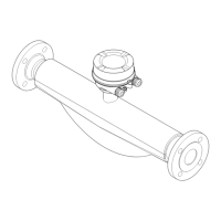
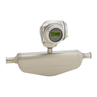
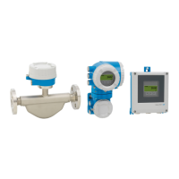
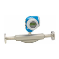
Wiring Proline Promass 83 PROFIBUS DP/PA
30 Endress+Hauser
4.2 Connecting the remote version
4.2.1 Connecting connecting cable for sensor/transmitter
#
Warning!
• Risk of electric shock. Switch off the power supply before opening the device.
Do not install or wire the device while it is connected to the power supply.
Failure to comply with this precaution can result in irreparable damage to the electronics.
• Risk of electric shock. Connect the protective earth to the ground terminal on the housing before
the power supply is applied.
• You may only connect the sensor to the transmitter with the same serial number. Communication
errors can occur if this is not observed when connecting the devices.
1. Remove the connection compartment cover (a) by loosening the fixing screws on the
transmitter and sensor housing.
2. Feed the connecting cable (b) through the appropriate cable runs.
3. Establish the connections between sensor and transmitter in accordance with the wiring
diagram:
– See Fig. 17
– See wiring diagram in screw cap
4. Screw the connection compartment cover (a) back onto the sensor and transmitter housing.
F06-8xxxxxxx-04-xx-xx-en-000
Fig. 17: Connecting the remote version
a Covers of the connection compartments (transmitter, sensor)
b Connecting cable (signal cable)
4.2.2 Cable specification for connecting cable
The specifications of the cable connecting the transmitter and the sensor of the remote version are
as follows:
• 6 x 0.38 mm
2
PVC cable with common shield and individually shielded cores
• Conductor resistance: ≤ 50 Ω/km
• Capacitance core/shield: ≤ 420 pF/m
• Cable length: max. 20 m
• Permanent operating temperature: max. +105 °C
!
Note!
The cable must be installed securely, to prevents movement.
6
47
58910
11 12
6
47
58910
11 12
41 42
41 42
S1
++ ++
S1 S2 S2
TM TM TT TT
GND
Pipe
S1
++ ++
S1 S2 S2
TM TM TT TT
GND
Pipe
a
b
a
brn
brn
wht
wht
grn
grn
gry
gry
yel
yel
pnk
pnk

 Loading...


