iPAK2 User Guide
34
4.3. Current calibration
Current is measured by one of two methods:
1. Primary current is measured by the iPAK2 built-in CT.
2. Secondary current can be measured via an externally connected Toroid (spot weld
modes only).
The method is selected by the Configuration parameter Measure.
4.3.1. Maximum Primary Current
The inverter chassis has a maximum output current specification dependant on the inverter
size. The iPAK2 detects this value on power-up and sets it as an absolute maximum. The
output current can be set below this maximum value. It is important to do this before
attempting any of the following calibration procedures (see Configuration section).
4.3.2. Current measurement by built-in CT
In order to display secondary current, there are two methods provided for conversion:
1. Turns ratio: The turns ratio may be obtained from the welding transformer data. The
displayed secondary current will be the measured primary current multiplied by this
value. This method does not allow for losses in the transformer but will provide reasonable
accuracy.
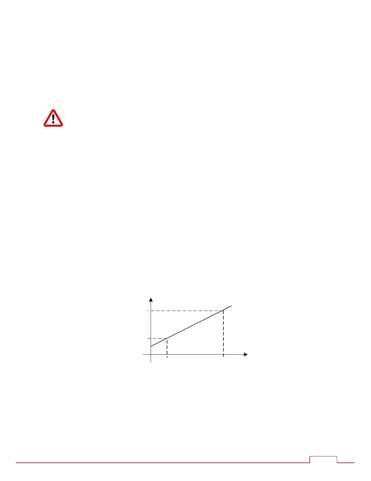
2. Points 1&2: This is the more accurate method and also calibrates the iPAK2 to match an
external current meter. Two test welds establish the relationship between primary current
(as measured by the CT) and secondary current measured using the external meter as
follows:
Initially, select the turns-ratio method and set the turn ratio to 1:1 so that the iPAK2
measures and displays primary current.
Produce a short circuit weld at a low heat in CCu mode and note the primary
current (Ip1) from the iPAK2 and the corresponding secondary current (Is1) using an
external weld current meter.
Repeat the short circuit weld at a higher heat and note again the primary current
(Ip2) and secondary current (Is2).
Now select the Points 1&2 method and enter the four measurements (Ip1, Is1 and
Ip2, Is2).
The iPAK2 uses the characteristic to calculate the secondary current from the measured
primary current.
I
p
I
s1
I
s
I
p2
I
p1
I
s2