iPAK2 User Guide
42
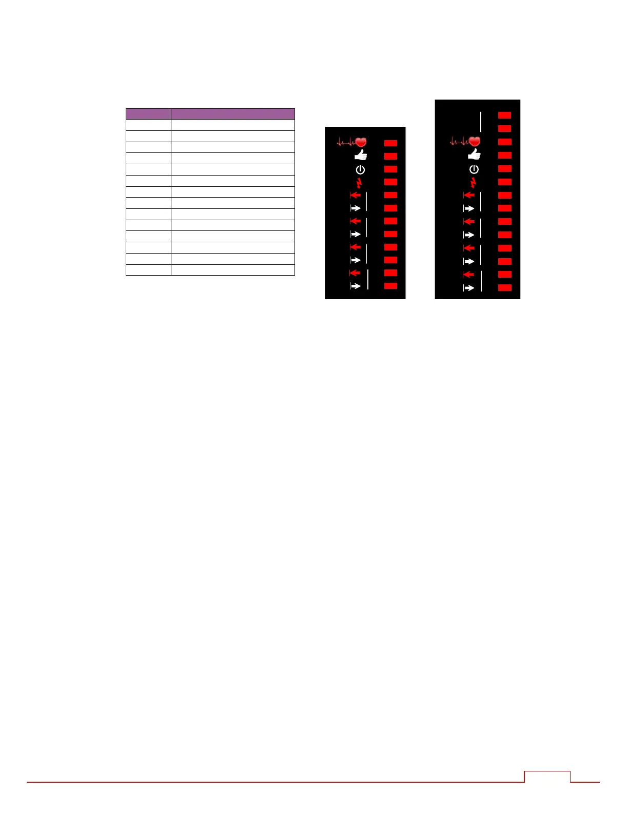
5.6. LED indicators
An array of LEDs, visible on the side of the control indicate activity:
LED FUNCTION
MS
1
EtherNet/IP module status
NS
1
EtherNet/IP network status
1 Heartbeat (Flashes at 1 Hz)
2 Ready (Flashes at 1Hz)
3 Sequence initiated
4 Weld current
5 Data receive COM0/4
6 Data send COM0/4
7 Data receive COM1/5
8 Data send COM1/5
9 Data receive COM2
10 Data send COM2
11 Data receive COM3
12 Data send COM3
1
On v2 model only. This same indicator
is visible on the adapter board (if fitted)
on non-v2 model.
5.6.1. Heartbeat LED (1)
This LED should always be flashing at 1Hz. The duty indicates:
Long ON, short OFF: The control is in BIOS only mode. Use NetFlash to install an
application.
Short ON, long OFF: The control is running an application.
5.6.2. Ready LED (2)
Flashing at 1 Hz: The control is ready for use.
Off: The control is not Ready. Check status messages.
5.6.3. Sequence LED (3)
The control has accepted a START signal and is running a weld program
5.6.4. Weld LED (4)
Lights when the control turns on the welding current.
5.6.5. Data Send/Receive LEDs (5…12)
Indicates activity on this COM port.
5.6.6. NS/MS LEDs
See EtherNet/IP section.
iPAK2 iPAK2v2
1
2
3
4
5
6
7
8
9
10
11
12
COM0
COM1
COM2
COM3
1
2
3
4
5
6
7
8
9
10
11
12
COM4
COM5
COM2
COM3
MS
NS
EtherNet/IP