iPAK2 User Guide
70
13.2. Testing the weld current
13.2.1. Current monitor
The current for each weld can be tested against upper and lower limits.
1. In the weld program, enable the Test current option for each weld to be
tested.
2. Set the Low limit and High limits appropriately. The limits correspond to a
percentage of the required current.
If the weld current falls outside the limits, iPAK2 will signal a fault.
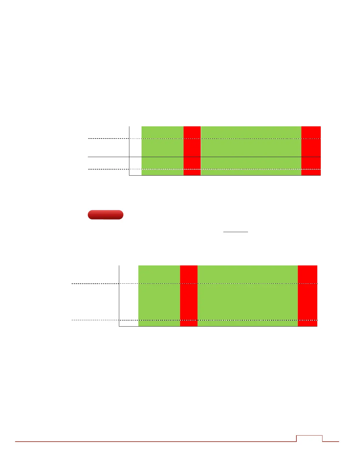
Current
Pass Fault Pass Fault
High limit
Target
Low limit
Spots
13.2.2. Conduction monitor (C-Monitor)
The control measures the percentage conduction of the Main-heat interval. The user may
set low (shunt) and high(wear) limits, thus setting an acceptance window. These limits are
absolute values (they are not percentages of the measurement). If the measured
conduction is found to be outside of these limits, the iPAK2 will signal a fault.
%Conduction
Pass Fault Pass Fault
Wear
limit
Shunt
limit
Spots
When using constant current, the conduction will vary as the control applies
compensation. Low conduction can be indicative of a shunt condition on the welding
transformer secondary circuit. High conduction can be indicative of secondary circuit
wear. Be sure to use CCR mode for the main heat
Extended