Expression 10000XL Revision A
OPERATING PRINCIPLES Mechanism Operation Overview 22
2.2 Mechanism Operation Overview
The optical system mechanism that scans the image of this scanner uses the Carriage
Unit where the light source, CCD Sensor Board, AF lens, and Mirrors move together.
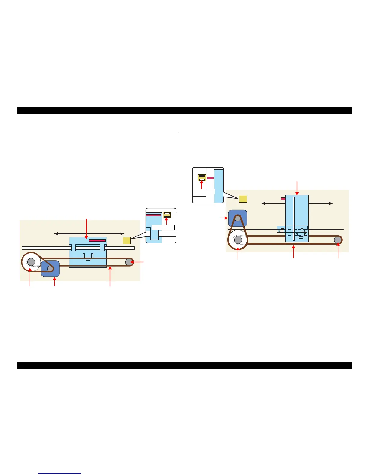
2.2.1 Carriage Drive System Mechanism
The Carriage Unit slides along the Guide Rail in the sub scanning direction. To
perform this sliding operation, the CR (Carriage) Motor transmits its driving force to
the Timing Belt secured to the Carriage Unit via the Drive Pulley and Deceleration
Gear. The starting position of image data scanning is determined by the CR HP Sensor
located on the Control Board.
A stepping motor is used as the CR Motor and driven by open loop control. (Refer to
Figure 2-2.)
Figure 2-2. Carriage Operation
2.2.2 TPU Carriage Movement Mechanism
The TPU Carriage Unit slides along the Guide Rail in the sub scanning direction. To
perform this sliding operation, the TPU CR (Carriage) Motor transmits its driving force
to the TPU CR Timing Belt secured to the Carriage Unit via the Drive Pulley and
Deceleration Gear.A stepping motor is used as the TPU CR Motor and driven by open
loop control.(Refer to Figure 2-3.)
Figure 2-3. TPU Carriage Operation
HP Sensor
CR Timing Belt
Driven Pulley
Carriage Unit
Drive Pulley CR Motor
Front Rear
HP Sensor
Front Rear
TPU Carriage Unit
Drive Pulley
TPU CR Motor
TPU CR Timing Belt Driven Pulley
 Loading...