Expression 10000XL Revision A
DISASSEMBLY/ASSEMBLY Disassembly Procedure 36
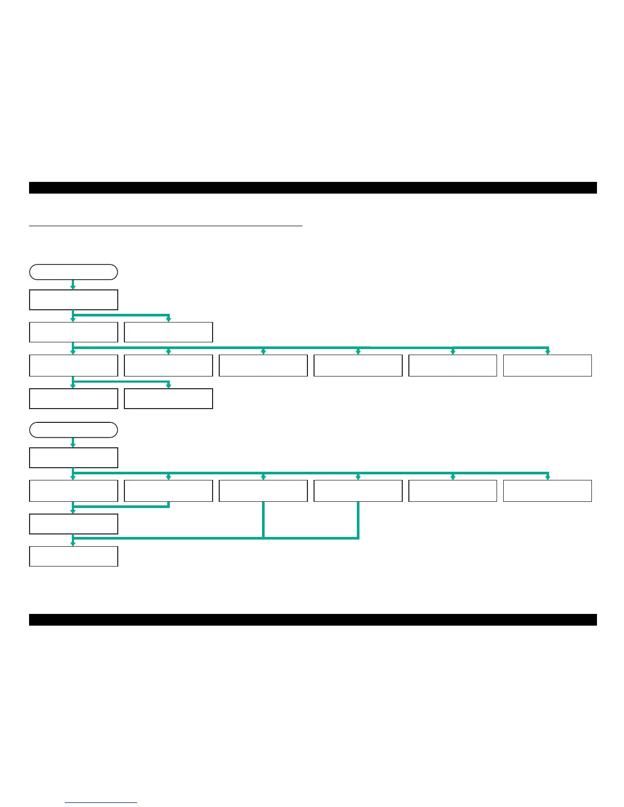
4.2 Disassembly Procedure
This section illustrates how to remove the main components of this product. Unless otherwise specified, the reassembly procedure is omitted here since the product can be
reassembled in the reverse order of the disassembly procedure. For the engagement of the main components, refer to the general exploded views in the Appendix.
Figure 4-2. Disassembly Procedure Flowchart
Start
Removal of Document Cover
(P.37)
Removal of Housing Upper
(P.38)
Removal of Carriage Unit and
Carriage Shaft A/B (P.44)
Removal of Power Supply
Board (P.39)
Removal of Main Board
(P.42)
Removal of Fan (P.46) Removal of Power Switch
(P.47)
Removal of Panel Board
(P.48)
Removal of HP Tension Unit/
CR Motor (P.48)
Removal of Open/Close
Sensor Unit (P.50)
Removal of TPU Lower
Housing (P.52)
Removal of TPU CR Motor
Belt/TPU CR Motor (P.55)
Removal of TPU Carriage
Unit (P.57)
Removal of OPTION I/F
Connector Cable (P.55)
Removal of TPU Main Board
(P.53)
Removal of TPU Carriage
Lock (P.53)
Removal of TPU Inverter
Board/Lamp (P.59)
Removal of TPU CR Belt
(P.60)
Removal of Hinges
(P.61)
Removal of Hinges
(P.37)
Start
Removal of Fan (P.46)
 Loading...